HP ENVY TouchSmart Sleekbook 4-1115dx HP ENVY 4 Sleekbook HP ENVY 4 Ultrabook - Page 60
WLAN module, Remove the 1 Phillips PM 2.0×2.5 screw
 |
View all HP ENVY TouchSmart Sleekbook 4-1115dx manuals
Add to My Manuals
Save this manual to your list of manuals |
Page 60 highlights
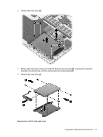
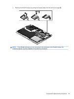
WLAN module Description Spare part number Intel® Centrino® Wireless-N 1030 + Bluetooth combo w/ *2 antennas (802.11 b/g/n, Bluetooth 3.0) 670290-005 Atheros 9485GN 802.11b/g/n 1×1 WiFi and 3012 Bluetooth 4.0 Combo Adapter 655795-005 Broadcom 4313GN 802.11b/g/n 1×1 WiFi and 20702 Bluetooth 4.0 Combo Adapter 657325-005 802.11 b/g/n HMC 1×1 WiFi adapter 675794-005 Atheros AR9565 802.11 b/g/n 1×1 WiFi Adapter 690019-005 Ralink 802.11 b/g/n 1×1 WiFi + Bluetooth 4.0 Combo Adapter 690020-005 Atheros HB125 802.11 b/g/n 1×1 WiFi + Bluetooth 4.0 Combo Adapter for use in Brazil 699834-201 CAUTION: To prevent an unresponsive system, replace the wireless module only with a wireless module authorized for use in the computer by the governmental agency that regulates wireless devices in your country or region. If you replace the module and then receive a warning message, remove the module to restore device functionality, and then contact technical support. Before removing the WLAN module, follow these steps: 1. Shut down the computer. If you are unsure whether the computer is off or in Hibernation, turn the computer on, and then shut it down through the operating system. 2. Disconnect all external devices connected to the computer. 3. Disconnect the power from the computer by first unplugging the power cord from the AC outlet and then unplugging the AC adapter from the computer. 4. Remove the display panel (see Display panel on page 39). 5. Remove the base enclosure (see Base enclosure on page 42). 6. Disconnect the battery cable (see Battery on page 43). Remove the WLAN module: 1. Disconnect the #1 and #2 WLAN antenna cables from the WLAN module (1). NOTE: The #1 WLAN antenna cable is connected to the WLAN module #1 main terminal. The #2 WLAN antenna cable is connected to the WLAN module #2 auxiliary terminal. 2. Remove the 1 Phillips PM 2.0×2.5 screw (2) that secures the WLAN module to the system board. (The WLAN module tilts up.) 52 Chapter 4 Removal and replacement procedures
-
 1
1 -
2
-
3
-
4
-
5
-
6
-
7
-
8
-
9
-
10
-
11
-
12
-
13
-
14
-
15
-
16
-
17
-
18
-
19
-
20
-
21
-
22
-
23
-
24
-
25
-
26
-
27
-
28
-
29
-
30
-
31
-
32
-
33
-
34
-
35
-
36
-
37
-
38
-
39
-
40
-
41
-
42
-
43
-
44
-
45
-
46
-
47
-
48
-
49
-
50
-
51
-
52
-
53
-
54
-
 55
55 -
 56
56 -
 57
57 -
 58
58 -
 59
59 -
 60
60 -
 61
61 -
 62
62 -
 63
63 -
 64
64 -
 65
65 -
66
-
67
-
68
-
69
-
70
-
71
-
72
-
73
-
74
-
75
-
76
-
77
-
78
-
79
-
80
-
81
-
82
-
83
-
84
-
85
-
86
-
87
-
88
-
89
-
90
-
91
-
92
-
93
-
94
-
95
-
96
-
97
-
98
-
99
-
100
-
101
-
102
-
103
-
104
-
105
-
106
-
107
-
108
-
109
-
110
-
111
-
112
-
113
-
114
-
115
-
116
 |
 |
