HP ENVY m6-k010dx HP ENVY m6 Sleekbook HP ENVY Touchsmart m6 SleekBook HP ENVY - Page 52
Card reader board, Remove the service cover see
 |
View all HP ENVY m6-k010dx manuals
Add to My Manuals
Save this manual to your list of manuals |
Page 52 highlights
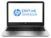
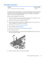
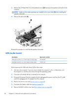
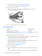
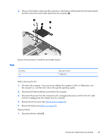
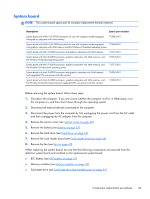
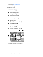
6. Remove the RJ-45 module cover (see RJ-45 module cover on page 40). 7. Remove the USB/audio board (see USB/audio board on page 42). Remove the power connector cable: ▲ Remove the power connector cable from its routing path (1), and then remove the power connector and cable (2) from the computer. Reverse this procedure to install the power connector and cable. Card reader board Description Card reader board for use only in Intel models Card reader board for use only in AMD models Spare part number 728133-001 727465-001 Before removing the card reader board, follow these steps: 1. Shut down the computer. If you are unsure whether the computer is off or in Hibernation, turn the computer on, and then shut it down through the operating system. 2. Disconnect all external devices connected to the computer. 3. Disconnect the power from the computer by first unplugging the power cord from the AC outlet and then unplugging the AC adapter from the computer. 4. Remove the service cover (see Service cover on page 30). 5. Remove the battery (see Battery on page 32). Remove the card reader board: 1. Remove the 2 Phillips PM2.0×2.0 screws that secure the card reader board to the system board (1). 2. Remove the Phillips PM2.5×3.5 screw that secures the card reader board to the computer (2). 44 Chapter 4 Removal and replacement procedures
-
 1
1 -
2
-
3
-
4
-
5
-
6
-
7
-
8
-
9
-
10
-
11
-
12
-
13
-
14
-
15
-
16
-
17
-
18
-
19
-
20
-
21
-
22
-
23
-
24
-
25
-
26
-
27
-
28
-
29
-
30
-
31
-
32
-
33
-
34
-
35
-
36
-
37
-
38
-
39
-
40
-
41
-
42
-
43
-
44
-
45
-
46
-
 47
47 -
 48
48 -
 49
49 -
 50
50 -
 51
51 -
 52
52 -
 53
53 -
 54
54 -
 55
55 -
 56
56 -
 57
57 -
58
-
59
-
60
-
61
-
62
-
63
-
64
-
65
-
66
-
67
-
68
-
69
-
70
-
71
-
72
-
73
-
74
-
75
-
76
-
77
-
78
-
79
-
80
-
81
-
82
-
83
-
84
-
85
-
86
-
87
-
88
-
89
-
90
-
91
-
92
-
93
-
94
-
95
-
96
 |
 |