HP ENVY m7-k200 Maintenance and Service Guide - Page 54
near the display hinge., Some models may have three screws in the optical drive bay
 |
View all HP ENVY m7-k200 manuals
Add to My Manuals
Save this manual to your list of manuals |
Page 54 highlights
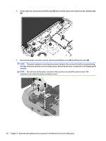
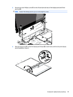
2. Remove eleven Phillips screws (1). 3. Remove eight Phillips screws (1) around the battery area, two broadhead screws (2) in the optical drive bay and one screw (3) near the display hinge. NOTE: Some models may have three screws in the optical drive bay (2). 44 Chapter 6 Removal and replacement procedures for Authorized Service Provider parts
-
 1
1 -
2
-
3
-
4
-
5
-
6
-
7
-
8
-
9
-
10
-
11
-
12
-
13
-
14
-
15
-
16
-
17
-
18
-
19
-
20
-
21
-
22
-
23
-
24
-
25
-
26
-
27
-
28
-
29
-
30
-
31
-
32
-
33
-
34
-
35
-
36
-
37
-
38
-
39
-
40
-
41
-
42
-
43
-
44
-
45
-
46
-
47
-
48
-
 49
49 -
 50
50 -
 51
51 -
 52
52 -
 53
53 -
 54
54 -
 55
55 -
 56
56 -
 57
57 -
 58
58 -
 59
59 -
60
-
61
-
62
-
63
-
64
-
65
-
66
-
67
-
68
-
69
-
70
-
71
-
72
-
73
-
74
-
75
-
76
-
77
-
78
-
79
-
80
-
81
-
82
-
83
-
84
-
85
-
86
-
87
-
88
-
89
-
90
-
91
-
92
-
93
-
94
-
95
-
96
-
97
-
98
-
99
-
100
-
101
-
102
-
103
-
104
-
105
-
106
-
107
-
108
-
109
-
110
-
111
-
112
-
113
-
114
-
115
-
116
-
117
-
118
-
119
-
120
 |
 |

2.
Remove eleven Phillips screws
(1)
.
3.
Remove eight Phillips screws
(1)
around the battery area, two broadhead screws
(2)
in the optical drive
bay and one screw
(3)
near the display hinge.
NOTE:
Some models may have three screws in the optical drive bay
(2)
.
44
Chapter 6
Removal and replacement procedures for Authorized Service Provider parts