HP EliteDesk 800 G5 Hardware Reference Guide
HP EliteDesk 800 G5 Manual
 |
View all HP EliteDesk 800 G5 manuals
Add to My Manuals
Save this manual to your list of manuals |
HP EliteDesk 800 G5 manual content summary:
- HP EliteDesk 800 G5 | Hardware Reference Guide - Page 1
Hardware Reference Guide - HP EliteDesk 800 G5 | Hardware Reference Guide - Page 2
. Some features may not be available on your product. To access the latest user guide, go to http://www.hp.com/support, and follow the instructions to find your product. Then select User Guides. Software terms By installing, copying, downloading, or otherwise using any software product preinstalled - HP EliteDesk 800 G5 | Hardware Reference Guide - Page 3
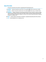
About This Guide This guide provides basic information for upgrading the HP ProDesk Business PC. WARNING! Indicates a hazardous situation that, if not avoided, could result in serious injury or death. CAUTION: Indicates a hazardous situation that, if not - HP EliteDesk 800 G5 | Hardware Reference Guide - Page 4
iv About This Guide - HP EliteDesk 800 G5 | Hardware Reference Guide - Page 5
location ...3 2 Hardware upgrades ...4 Serviceability features ...4 Warnings and cautions ...4 bezel dust filter 10 Changing from desktop to tower orientation ...12 System board connectors ...13 Upgrading 40 Padlock ...40 HP Business PC Security Lock V2 ...41 Appendix A Battery replacement ...46 - HP EliteDesk 800 G5 | Hardware Reference Guide - Page 6
Finding the best assistive technology 54 Assessing your needs ...54 Accessibility for HP products 54 Standards and legislation ...55 Standards ...55 Mandate 376 - ...58 Educational institutions ...58 Other disability resources ...58 HP links ...58 Contacting support ...59 Index ...60 vi - HP EliteDesk 800 G5 | Hardware Reference Guide - Page 7
Features may vary depending on the model. For support assistance and to learn more about the hardware and software installed on your computer model, run the HP Support Assistant utility. NOTE: This computer model can be used in a tower orientation or a desktop orientation. See Changing from desktop - HP EliteDesk 800 G5 | Hardware Reference Guide - Page 8
Front panel components 1 Slim optical drive (optional) 6 USB port with HP Sleep and Charge 2 SD card reader (optional) 7 Audio-out (headphone , there is a problem with the computer and it is displaying a diagnostic code. See the Maintenance and Service Guide to interpret the code. 2 - HP EliteDesk 800 G5 | Hardware Reference Guide - Page 9
, or smartwatch. NOTE: Your model may have additional optional ports available from HP. When a graphics card is installed in one of the system board slots, . The system board graphics can be disabled by changing settings in BIOS F10 Setup. Serial number location Each computer has a unique serial - HP EliteDesk 800 G5 | Hardware Reference Guide - Page 10
to upgrade and service. A Torx T15 or flat-bladed screwdriver is needed for some of the installation procedures described in this chapter. Warnings and cautions Before performing upgrades be sure to carefully read all of the applicable instructions, cautions, and warnings in this guide. WARNING! To - HP EliteDesk 800 G5 | Hardware Reference Guide - Page 11
IMPORTANT: Regardless of the power-on state, voltage is always present on the system board as long as the system is plugged into an active AC outlet. You must disconnect the power cord to avoid damage to the internal components of the computer. Removing the computer access panel To access internal - HP EliteDesk 800 G5 | Hardware Reference Guide - Page 12
Replacing the computer access panel Be sure that the access panel release lever is locked into place, and then place the access panel on the computer (1) and slide the panel (2) forward. The release lever will automatically move back to the right and lock the access panel. 6 Chapter 2 Hardware - HP EliteDesk 800 G5 | Hardware Reference Guide - Page 13
Removing the front bezel 1. Prepare the computer for disassembly. See Preparing for disassembly on page 4. 2. Remove the computer access panel. See Removing the computer access panel on page 5. 3. Lift up the three tabs on the top of the bezel (1), and then rotate the bezel off the chassis (2). - HP EliteDesk 800 G5 | Hardware Reference Guide - Page 14
Removing a slim optical drive bezel blank On some models, a bezel blank covers the slim optical drive bay. Remove the bezel blank before installing an optical drive. To remove the bezel blank: 1. Prepare the computer for disassembly. See Preparing for disassembly on page 4. 2. Remove the computer - HP EliteDesk 800 G5 | Hardware Reference Guide - Page 15
Replacing the front bezel Insert the three hooks on the bottom of the bezel (1) into the rectangular holes on the chassis, and then rotate the top of the bezel onto the chassis (2) and snap it into place. Replacing the front bezel 9 - HP EliteDesk 800 G5 | Hardware Reference Guide - Page 16
dust collected on the filter does not impede air flow through the computer. NOTE: The optional front bezel dust filter is available from HP. To remove, clean, and replace the dust filter: 1. Prepare the computer for disassembly. See Preparing for disassembly on page 4. 2. Remove the computer access - HP EliteDesk 800 G5 | Hardware Reference Guide - Page 17
6. To replace the dust filter, press the filter firmly onto the front bezel at the tab locations shown below. 7. Reconnect the power cord and any external devices, and then turn on the computer. Removing and installing the optional front bezel dust filter 11 - HP EliteDesk 800 G5 | Hardware Reference Guide - Page 18
The Small Form Factor computer can be used in a tower orientation with an optional tower stand that can be purchased from HP. NOTE: To stabilize the computer in a tower orientation, HP recommends the use of the optional tower stand. 1. Prepare the computer for disassembly. See Preparing for - HP EliteDesk 800 G5 | Hardware Reference Guide - Page 19
System board connectors Refer to the following illustration and table to identify the system board connectors for your model. Table 2-1 System board connectors Item System board connector System board label 1 PCI Express ×16 downshifted to ×4PCIEXP a ×4 2 PCI Express ×1 ×1PCIEXP2 3 PCI - HP EliteDesk 800 G5 | Hardware Reference Guide - Page 20
memory modules (DIMMs). The memory sockets on the system board are populated with at least one preinstalled memory module. To achieve the maximum memory support, you can populate the system board with up to 128 GB of memory configured in a high-performing dual-channel mode. The maximum single-module - HP EliteDesk 800 G5 | Hardware Reference Guide - Page 21
DIMM and one 1 GB DIMM, and Channel B should be populated with the other two 1 GB DIMMs. With this configuration, 4 GB will run as dual-channel and 1 GB will run as single-channel. ● In any mode, the maximum operational speed is determined by the slowest DIMM in the system. IMPORTANT: You must - HP EliteDesk 800 G5 | Hardware Reference Guide - Page 22
3. Open both latches (1) of the memory module socket, and insert the memory module into the socket (2). Press the module down into the socket, ensuring that the module is fully inserted and properly seated. Make sure the latches are in the closed position (3). NOTE: A memory module can be installed - HP EliteDesk 800 G5 | Hardware Reference Guide - Page 23
, one PCI Express ×16 expansion socket, and one PCI Express ×16 expansion socket that is downshifted to a ×4 socket. NOTE: The PCI Express sockets support only low profile cards. You can install a PCI Express ×1, ×4, ×8, or ×16 expansion card in the PCI Express ×16 socket. For dual graphics card - HP EliteDesk 800 G5 | Hardware Reference Guide - Page 24
b. If you are removing a PCI Express ×1 card, hold the card at each end and carefully rock it back and forth until the connectors pull free from the socket. Lift the card (1) straight up then away from the inside of the chassis (2) to remove it. Be sure not to scrape the card against other - HP EliteDesk 800 G5 | Hardware Reference Guide - Page 25
c. If you are removing a PCI Express ×16 card, pull the retention arm on the back of the expansion socket away from the card (1) and carefully rock the card back and forth until the connectors pull free from the socket. Lift the card (2) straight up then away from the inside of the chassis (3) to - HP EliteDesk 800 G5 | Hardware Reference Guide - Page 26
9. To install a new expansion card, hold the card just above the expansion socket on the system board then move the card toward the rear of the chassis (1) so that the bottom of the bracket on the card slides into the small slot on the chassis. Press the card straight down into the expansion socket - HP EliteDesk 800 G5 | Hardware Reference Guide - Page 27
12. Replace the computer access panel. 13. If the computer was on a stand, replace the stand. 14. Reconnect the power cord and any external devices, and then turn on the computer. 15. Lock any security devices that were disengaged when the access panel was removed. 16. Reconfigure the computer, if - HP EliteDesk 800 G5 | Hardware Reference Guide - Page 28
IMPORTANT: To prevent loss of work and damage to the computer or drive: If you are inserting or removing a drive, shut down the operating system properly, turn off the computer, and unplug the power cord. Do not remove a drive while the computer is on or in standby mode. Before handling a drive, be - HP EliteDesk 800 G5 | Hardware Reference Guide - Page 29
5. Push the green release latch on the right rear side of the drive toward the center of the drive (1), and then slide the drive forward and out of the bay (2). Removing and installing drives 23 - HP EliteDesk 800 G5 | Hardware Reference Guide - Page 30
Installing a 9.5 mm slim optical drive 1. Prepare the computer for disassembly. See Preparing for disassembly on page 4. 2. If the computer is on a stand, remove the computer from the stand. 3. Remove the computer access panel. See Removing the computer access panel on page 5. 4. If you are - HP EliteDesk 800 G5 | Hardware Reference Guide - Page 31
6. Slide the optical drive through the front bezel all the way into the bay (1) so that the latch on the rear of the drive locks into place (2). 7. Connect the power cable (1) and data cable (2) to the rear of the drive. 8. Connect the opposite end of the data cable to one of the light-blue SATA - HP EliteDesk 800 G5 | Hardware Reference Guide - Page 32
12. Reconnect the power cord and any external devices, and then turn on the computer. 13. Lock any security devices that were disengaged when the access panel was removed. Removing a 3.5-inch hard drive NOTE: Before you remove the old hard drive, be sure to back up the data from the old hard drive - HP EliteDesk 800 G5 | Hardware Reference Guide - Page 33
5. Pull the release lever next to the rear of the hard drive outward (1). While pulling the release lever out, lift the rear of the drive up (2), and then slide the front of the drive back and lift it out of the bay (3). 6. Remove the four mounting screws (two on each side) from the old drive. You - HP EliteDesk 800 G5 | Hardware Reference Guide - Page 34
from the old hard drive to the new hard drive. If you are adding a second 3.5-inch hard drive, you can purchase extra mounting screws from HP. ● Install four silver-and-blue 6-32 mounting screws (two on each side of the drive). ● You can also install a 2.5-inch hard drive into a 3.5-inch drive - HP EliteDesk 800 G5 | Hardware Reference Guide - Page 35
- Secure the drive to the bay adapter bracket by installing four black M3 adapter bracket screws through the underside of the bracket and into the drive. Removing and installing drives 29 - HP EliteDesk 800 G5 | Hardware Reference Guide - Page 36
- Install four 6-32 silver-and-blue mounting screws in the adapter bracket (two on each side of the bracket). 5. Align the mounting screws on the front of the hard drive with the slots on the drive cage and press the front of the drive down and forward into the bay (1). Then press the rear of the - HP EliteDesk 800 G5 | Hardware Reference Guide - Page 37
6. Connect the power cable (1) and data cable (2) to the rear of the hard drive. NOTE: If the 3.5-inch hard drive is the primary drive, connect the other end of the data cable to the dark-blue SATA connector on the system board labeled SATA0. If it is a secondary hard drive, connect the other end of - HP EliteDesk 800 G5 | Hardware Reference Guide - Page 38
Removing a 2.5-inch hard drive 1. Prepare the computer for disassembly. See Preparing for disassembly on page 4. 2. If the computer is on a stand, remove the computer from the stand. 3. Remove the computer access panel. See Removing the computer access panel on page 5. 4. Remove the front bezel. 5. - HP EliteDesk 800 G5 | Hardware Reference Guide - Page 39
7. Pull the release lever at the rear of the drive outward (1). Then slide the drive back until it stops and pull it down and out of the drive bay (2). 8. If you are installing a new drive, refer to Installing a 2.5-inch hard drive on page 34. If you are not installing a new drive, rotate the drive - HP EliteDesk 800 G5 | Hardware Reference Guide - Page 40
bezel. 5. Install four black-and-blue M3 mounting screws (two on each side of the drive). NOTE: M3 metric mounting screws can be purchased from HP. When replacing a drive, transfer the four mounting screws from the old drive to the new drive. 34 Chapter 2 Hardware upgrades - HP EliteDesk 800 G5 | Hardware Reference Guide - Page 41
6. Rotate the drive cage to its upright position. 7. Align the mounting screws on the drive with the J-slots on the sides of the drive bay. Press the drive into the drive bay, and then slide the drive forward until it locks in place. Removing and installing drives 35 - HP EliteDesk 800 G5 | Hardware Reference Guide - Page 42
8. Connect the power cable (1) and data cable (2) to the rear of the hard drive. NOTE: If the 2.5-inch hard drive is the primary drive, connect the other end of the data cable to the dark-blue SATA connector on the system board labeled SATA0. If it is a secondary hard drive, connect the other end of - HP EliteDesk 800 G5 | Hardware Reference Guide - Page 43
the access panel was removed. Removing and installing an M.2 SSD storage card NOTE: There are two M.2 SSD sockets on the system board. The computer supports 2230 and 2280 M.2 SSD cards. 1. Prepare the computer for disassembly. See Preparing for disassembly on page 4. 2. If the computer is on a stand - HP EliteDesk 800 G5 | Hardware Reference Guide - Page 44
6. To remove an M.2 SSD card, remove the screw that secures the card (1), lift the end of the card up (2), and then slide the card out of the system board connector (3). 7. To install an M.2 SSD card, slide the pins on the card into the system board connector while holding the card at approximately - HP EliteDesk 800 G5 | Hardware Reference Guide - Page 45
8. Rotate the drive cage back down to its normal position. IMPORTANT: Be careful not to pinch any cables or wires when rotating the drive cage down. 9. Replace the front bezel. 10. Replace the computer access panel. 11. If the computer was on a stand, replace the stand. 12. Reconnect the power cord - HP EliteDesk 800 G5 | Hardware Reference Guide - Page 46
Installing a security lock The security locks displayed below and on the following pages can be used to secure the computer. Cable lock Padlock 40 Chapter 2 Hardware upgrades - HP EliteDesk 800 G5 | Hardware Reference Guide - Page 47
PC Security Lock V2 The HP PC Security Lock V2 is designed to secure all of the devices at your workstation. 1. Attach the security cable fastener to a desktop using the appropriate - HP EliteDesk 800 G5 | Hardware Reference Guide - Page 48
the security slot on the rear of the monitor (1), close the scissor hands together to secure the lock in place (2), and then slide the cable guide through the center of the monitor lock (3). 42 Chapter 2 Hardware upgrades - HP EliteDesk 800 G5 | Hardware Reference Guide - Page 49
5. Slide the security cable through the security guide installed on the monitor. 6. Attach the accessory cable fastener to a desktop using the appropriate screw for your environment (screw not provided) (1), and then place the - HP EliteDesk 800 G5 | Hardware Reference Guide - Page 50
7. Slide the security cable through the holes in the accessory cable fastener. 8. Screw the lock to the chassis using the screw provided. 44 Chapter 2 Hardware upgrades - HP EliteDesk 800 G5 | Hardware Reference Guide - Page 51
9. Insert the plug end of the security cable into the lock (1) and push the button in (2) to engage the lock. Use the key provided to disengage the lock. 10. When you have completed all steps, all of the devices at your workstation will be secured. Installing a security lock 45 - HP EliteDesk 800 G5 | Hardware Reference Guide - Page 52
, or dispose of in fire or water. Replace the battery only with the HP spare designated for this product. IMPORTANT: Before replacing the battery, it is important holder on the system board, complete the following instructions to replace the battery. Type 1 a. Lift the battery out of its holder - HP EliteDesk 800 G5 | Hardware Reference Guide - Page 53
b. Slide the replacement battery into position, positive side up. The battery holder automatically secures the battery in the proper position. Type 2 a. To release the battery from its holder, squeeze the metal clamp that extends above one edge of the battery (1). When the battery pops up, lift it - HP EliteDesk 800 G5 | Hardware Reference Guide - Page 54
b. To insert the new battery, slide one edge of the replacement battery under the holder's lip with the positive side up (1). Push the other edge down until the clamp snaps over the other edge of the battery (2). Type 3 a. Pull back the clip (1) that is holding the battery in place, and remove the - HP EliteDesk 800 G5 | Hardware Reference Guide - Page 55
8. Reconnect the power cord and any external devices, and then turn on the computer. 9. Reset the date and time, your passwords, and any special system setups using Computer Setup. 10. Lock any security devices that were disengaged when the computer access panel was removed. 49 - HP EliteDesk 800 G5 | Hardware Reference Guide - Page 56
components. To prevent damage to the computer, damage to a drive, or loss of information, observe these precautions: ● If removal or installation instructions direct you to unplug the computer, first be sure that it is properly grounded. ● Keep components in their electrostatic-safe containers until - HP EliteDesk 800 G5 | Hardware Reference Guide - Page 57
C Computer operating guidelines, routine care and shipping preparation Computer operating guidelines and routine care Follow these guidelines to properly set up and care for the computer and monitor: ● Keep the computer away from excessive moisture, direct sunlight, and extremes of heat and cold. ● - HP EliteDesk 800 G5 | Hardware Reference Guide - Page 58
the finish. Safety If any object or liquid falls into the drive, immediately unplug the computer and have it checked by an authorized HP service provider. Shipping preparation Follow these suggestions when preparing to ship the computer: 1. Back up the hard drive files to an external storage - HP EliteDesk 800 G5 | Hardware Reference Guide - Page 59
. Our commitment HP is committed to providing products and services that are accessible for people with disabilities. This commitment supports our company's seven key objectives to guide our actions as a company. All HP managers and employees are expected to support these objectives and their - HP EliteDesk 800 G5 | Hardware Reference Guide - Page 60
HP is a founding member, and we joined to participate with other organizations to advance the field of accessibility. This commitment supports our company's accessibility goal of designing, producing, and marketing products and services that can be effectively used by people with disabilities. IAAP - HP EliteDesk 800 G5 | Hardware Reference Guide - Page 61
for public procurement of ICT products. The standard specifies the functional accessibility requirements applicable to ICT products and services, together with a description of the test procedures and evaluation methodology for each accessibility requirement. Web Content Accessibility Guidelines - HP EliteDesk 800 G5 | Hardware Reference Guide - Page 62
FCC and documented as 47 CFR Part 14 and Part 79. ● FCC Guide on the CVAA Other U.S. legislation and initiatives ● Americans with Disabilities Act ( organization, and to every other person or organization that provides goods, services, or facilities to the public or other third parties and that has - HP EliteDesk 800 G5 | Hardware Reference Guide - Page 63
teams to carry out the work specified in the European Commission "Mandate 376 to CEN, CENELEC and ETSI, in Support of Accessibility Requirements for Public Procurement of Products and Services in the ICT Domain." ETSI TC Human Factors Specialist Task Force 333 has developed ETSI DTR 102 612. Further - HP EliteDesk 800 G5 | Hardware Reference Guide - Page 64
Program ● Business & Disability network ● EnableMart ● European Disability Forum ● Job Accommodation Network ● Microsoft Enable ● U.S. Department of Justice - A Guide to disability rights Laws HP links Our contact webform HP comfort and safety guide HP public sector sales 58 Appendix D Accessibility - HP EliteDesk 800 G5 | Hardware Reference Guide - Page 65
through Friday, 6 a.m. to 9 p.m. Mountain Time. ● Customers with other disabilities or age-related limitations who have questions about technical support or accessibility of HP products, choose one of the following options: - Call (888) 259-5707 Monday through Friday, 6 a.m. to 9 p.m. Mountain Time - HP EliteDesk 800 G5 | Hardware Reference Guide - Page 66
C computer operating guidelines 51 customer support, accessibility 59 D drives cable connections of Accessibility Professionals 53 L locks cable lock 40 HP Business PC Security Lock 41 padlock 40 R rear memory installation 14 socket population 14 T tower conversion 12 V ventilation guidelines 51
-
 1
1 -
 2
2 -
 3
3 -
 4
4 -
 5
5 -
 6
6 -
 7
7 -
8
-
9
-
10
-
11
-
12
-
13
-
14
-
15
-
16
-
17
-
18
-
19
-
20
-
21
-
22
-
23
-
24
-
25
-
26
-
27
-
28
-
29
-
30
-
31
-
32
-
33
-
34
-
35
-
36
-
37
-
38
-
39
-
40
-
41
-
42
-
43
-
44
-
45
-
46
-
47
-
48
-
49
-
50
-
51
-
52
-
53
-
54
-
55
-
56
-
57
-
58
-
59
-
60
-
61
-
62
-
63
-
64
-
65
-
66
 |
 |

Hardware Reference Guide