HP G42-232NR Compaq Presario CQ42 Notebook PC and HP G42 Notebook PC - Mainten - Page 71
Memory modules are designed with a notch, Remove the module
 |
View all HP G42-232NR manuals
Add to My Manuals
Save this manual to your list of manuals |
Page 71 highlights
3. Lift cover off the computer. The mini-card compartment cover is included in the plastics kit, spare part number 600190-001. NOTE: Small tabs hold the cover in place. Firmly pull up on the cover to release the tabs. 4. Spread the retaining tabs (1) on each side of the memory module slot to release the memory module. (The edge of the module opposite the slot rises away from the computer.) 5. Remove the module (2) by pulling it away from the slot at an angle. NOTE: Memory modules are designed with a notch (3) to prevent incorrect insertion into the memory module slot. Reverse this procedure to install a memory module. ENWW Component replacement procedures 61
-
 1
1 -
2
-
3
-
4
-
5
-
6
-
7
-
8
-
9
-
10
-
11
-
12
-
13
-
14
-
15
-
16
-
17
-
18
-
19
-
20
-
21
-
22
-
23
-
24
-
25
-
26
-
27
-
28
-
29
-
30
-
31
-
32
-
33
-
34
-
35
-
36
-
37
-
38
-
39
-
40
-
41
-
42
-
43
-
44
-
45
-
46
-
47
-
48
-
49
-
50
-
51
-
52
-
53
-
54
-
55
-
56
-
57
-
58
-
59
-
60
-
61
-
62
-
63
-
64
-
65
-
 66
66 -
 67
67 -
 68
68 -
 69
69 -
 70
70 -
 71
71 -
 72
72 -
 73
73 -
 74
74 -
 75
75 -
 76
76 -
77
-
78
-
79
-
80
-
81
-
82
-
83
-
84
-
85
-
86
-
87
-
88
-
89
-
90
-
91
-
92
-
93
-
94
-
95
-
96
-
97
-
98
-
99
-
100
-
101
-
102
-
103
-
104
-
105
-
106
-
107
-
108
-
109
-
110
-
111
-
112
-
113
-
114
-
115
-
116
-
117
-
118
-
119
-
120
-
121
-
122
-
123
-
124
-
125
-
126
-
127
-
128
-
129
-
130
-
131
-
132
-
133
-
134
-
135
-
136
-
137
-
138
-
139
-
140
-
141
-
142
-
143
-
144
-
145
-
146
-
147
-
148
-
149
-
150
 |
 |
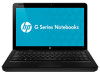
3.
Lift cover off the computer. The mini-card compartment cover is included in the plastics kit, spare
part number 600190-001.
NOTE:
Small tabs hold the cover in place. Firmly pull up on the cover to release the tabs.
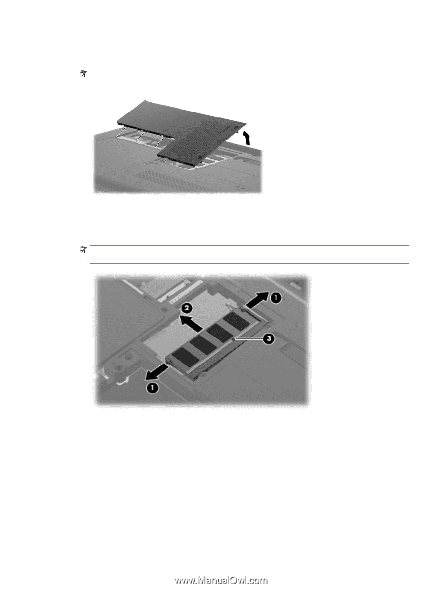
4.
Spread the retaining tabs
(1)
on each side of the memory module slot to release the memory
module. (The edge of the module opposite the slot rises away from the computer.)
5.
Remove the module
(2)
by pulling it away from the slot at an angle.
NOTE:
Memory modules are designed with a notch
(3)
to prevent incorrect insertion into the
memory module slot.
Reverse this procedure to install a memory module.
ENWW
Component replacement procedures
61