HP G60-231WM Service Guide - Page 66
following screw covers and screws
 |
View all HP G60-231WM manuals
Add to My Manuals
Save this manual to your list of manuals |
Page 66 highlights
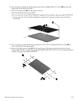
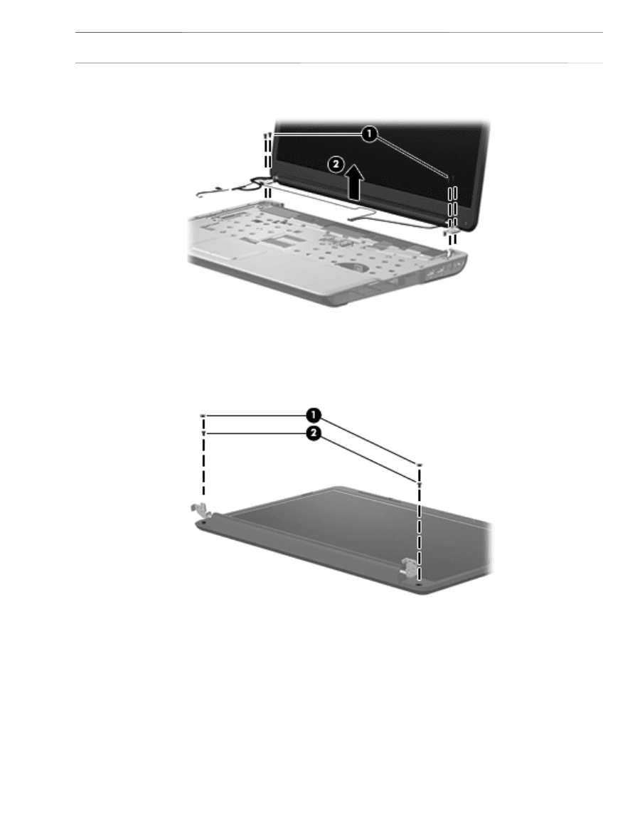
Ä CAUTION: Support the display assembly when removing the following screws. Failure to support the display assembly can result in damage to the display assembly and other computer components. 5. Remove the four Phillips PM2.5x9.0 screws 1 securing the display hinges to the computer. 6. Remove the display panel 2. 7. If it is necessary to replace the display bezel or any of the display assembly internal components, remove the following screw covers and screws: 1 Two rubber screw covers on the display bezel bottom edge. The display rubber screw covers are included in the Display Rubber Kit, spare part number 486584-001. 2 Two Phillips PM2.5x7.0 screws on the display bezel bottom edge. Removal and replacement procedures 4-25
-
 1
1 -
2
-
3
-
4
-
5
-
6
-
7
-
8
-
9
-
10
-
11
-
12
-
13
-
14
-
15
-
16
-
17
-
18
-
19
-
20
-
21
-
22
-
23
-
24
-
25
-
26
-
27
-
28
-
29
-
30
-
31
-
32
-
33
-
34
-
35
-
36
-
37
-
38
-
39
-
40
-
41
-
42
-
43
-
44
-
45
-
46
-
47
-
48
-
49
-
50
-
51
-
52
-
53
-
54
-
55
-
56
-
57
-
58
-
59
-
60
-
 61
61 -
 62
62 -
 63
63 -
 64
64 -
 65
65 -
 66
66 -
 67
67 -
 68
68 -
 69
69 -
 70
70 -
 71
71 -
72
-
73
-
74
-
75
-
76
-
77
-
78
-
79
-
80
-
81
-
82
-
83
-
84
-
85
-
86
-
87
-
88
-
89
-
90
-
91
-
92
-
93
-
94
-
95
-
96
-
97
-
98
-
99
-
100
-
101
-
102
-
103
-
104
-
105
-
106
-
107
-
108
-
109
-
110
-
111
-
112
-
113
-
114
-
115
-
116
-
117
-
118
-
119
-
120
-
121
-
122
-
123
-
124
-
125
-
126
-
127
-
128
-
129
-
130
-
131
-
132
-
133
-
134
-
135
-
136
-
137
-
138
 |
 |
Removal and replacement procedures
4–25
Ä
CAUTION:
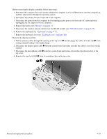
Support the display assembly when removing the following screws. Failure to support the display assembly can
result in damage to the display assembly and other computer components.
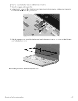
5. Remove the four Phillips PM2.5x9.0 screws
1
securing the display hinges to the computer.
6. Remove the display panel
2
.
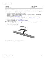
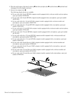
7. If it is necessary to replace the display bezel or any of the display assembly internal components, remove the
following screw covers and screws:
1
Two rubber screw covers on the display bezel bottom edge. The display rubber screw covers are included in
the Display Rubber Kit, spare part number 486584-001.
2
Two Phillips PM2.5x7.0 screws on the display bezel bottom edge.