HP G61-204TU Compaq Presario CQ61 Notebook PC and HP G61 Notebook PC - Mainten - Page 79
System board
 |
View all HP G61-204TU manuals
Add to My Manuals
Save this manual to your list of manuals |
Page 79 highlights
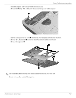
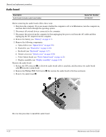
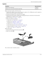
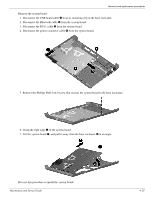
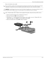
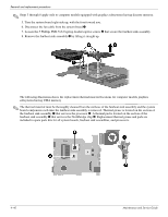
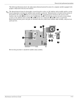
Removal and replacement procedures System board ✎ The system board spare part kit includes UMA or discrete graphics subsystem memory, built-in modem, and replacement thermal material. Description GM45 UMA system board (built-in modem, Digital Media Slot, and replacement thermal material) GM45 UMA system board (built-in modem, Digital Media Slot, HDMI port, and replacement thermal material) GL40 UMA system board (built-in modem, Digital Media Slot, and replacement thermal material) GL40 UMA system board (built-in modem, Digital Media Slot, HDMI port, and replacement thermal material) GL40 UMA system board (built-in modem, Digital Media Slot, HDMI port, and replacement thermal material) PM45 discrete system board (built-in modem, Digital Media Slot, HDMI port, and replacement thermal material) PM45 discrete system board PM45 (built-in modem, Digital Media Slot, and replacement thermal material) Spare part number 517832-001 517839-001 517836-001 517835-001 570246-001 517837-001 517838-001 Before removing the system board, follow these steps: 1. Shut down the computer. If you are unsure whether the computer is off or in Hibernation, turn the computer on, and then shut it down through the operating system. 2. Disconnect all external devices connected to the computer. 3. Disconnect the power from the computer by first unplugging the power cord from the AC outlet and then unplugging the AC adapter from the computer. 4. Remove the battery (see "Battery" on page 4-7). 5. Remove the following components: a. Optical drive (see "Optical drive" on page 4-8) b. Hard drive (see "Hard drive" on page 4-10) c. Keyboard (see "Keyboard" on page 4-17) d. Switch cover (see "Switch cover" on page 4-20) e. Power button board (see "Power button board" on page 4-22) f. Display assembly (see "Display assembly" on page 4-23) g. Top cover (see "Top cover" on page 4-30) When replacing the system board, be sure that the following components are removed from the defective system board and installed on the replacement system board: ■ Memory module (see "Memory module" on page 4-13) ■ Wireless module (see "Wireless module" on page 4-14) ■ Fan/heat sink assembly (see "Fan/heat sink assembly" on page 4-38) ■ Processor (see "Processor" on page 4-42) 4-36 Maintenance and Service Guide
-
 1
1 -
2
-
3
-
4
-
5
-
6
-
7
-
8
-
9
-
10
-
11
-
12
-
13
-
14
-
15
-
16
-
17
-
18
-
19
-
20
-
21
-
22
-
23
-
24
-
25
-
26
-
27
-
28
-
29
-
30
-
31
-
32
-
33
-
34
-
35
-
36
-
37
-
38
-
39
-
40
-
41
-
42
-
43
-
44
-
45
-
46
-
47
-
48
-
49
-
50
-
51
-
52
-
53
-
54
-
55
-
56
-
57
-
58
-
59
-
60
-
61
-
62
-
63
-
64
-
65
-
66
-
67
-
68
-
69
-
70
-
71
-
72
-
73
-
 74
74 -
 75
75 -
 76
76 -
 77
77 -
 78
78 -
 79
79 -
 80
80 -
 81
81 -
 82
82 -
 83
83 -
 84
84 -
85
-
86
-
87
-
88
-
89
-
90
-
91
-
92
-
93
-
94
-
95
-
96
-
97
-
98
-
99
-
100
-
101
-
102
-
103
-
104
-
105
-
106
-
107
-
108
-
109
-
110
-
111
-
112
-
113
-
114
-
115
-
116
-
117
-
118
-
119
-
120
-
121
-
122
-
123
-
124
-
125
-
126
-
127
-
128
-
129
-
130
-
131
-
132
-
133
-
134
-
135
-
136
-
137
 |
 |