HP GbE2c HP GbE2c Ethernet Blade Switch for c-Class BladeSystem Application Gu - Page 142
Configuring Uplink Failure Detection, Configuring UFD on Switch 1 (CLI example)
 |
UPC - 808736802215
View all HP GbE2c manuals
Add to My Manuals
Save this manual to your list of manuals |
Page 142 highlights
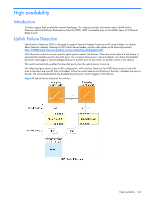
Configuring Uplink Failure Detection The preceding figure shows a basic UFD configuration. Port 21 on Blade Switch 1 is connected to a Layer 2/3 routing switch outside of the chassis. Port 20 and port 22 on Blade Switch 2 form a trunk that is connected to a different Layer 2/3 routing switch. The interconnect ports (17-18) are disabled. In this example, NIC 1 is the primary network adapter; NIC 2, NIC 3, and NIC 4 are non-primary adapters. NIC 1 and NIC 2 are connected to port 1 and port 2 on Blade Switch 1. NIC 3 and NIC 4 are connected to port 1 and port 2 on Blade Switch 2. Configuring UFD on Switch 1 (CLI example) 1. Assign uplink ports (20-24) to be monitored for communication failure. >> Main# /cfg/ufd/fdp ena (Enable Failure Detection Pair) >> FDP# ltm (Select Link to Monitor menu) >> Failure Link to Monitor# addport 21 (Monitor uplink port 21) 2. Assign downlink ports (1-16) to disable when an uplink failure occurs. >> /cfg/ufd/fdp/ltd (Select Link to Disable menu) >> Failure Link to Disable# addport 1 (Add port 1 as a Link to Disable) >> Failure Link to Disable# addport 2 (Add port 2 as a Link to Disable) 3. Turn UFD on. >> /cfg/ufd/on (Turn Uplink Failure Detection on) >> Uplink Failure Detection# apply (Make your changes active) >> Uplink Failure Detection# save (Save for restore after reboot) When a link failure or Spanning Tree blocking occurs on port 21, Switch 1 disables port 1 and port 2. Configuring UFD on Switch 2 (CLI example) 1. Create a trunk group of uplink ports (20-24) to monitor. First you must set each port to full duplex mode. >> Main# /cfg/port 20/gig/mode full (Set port 20 to full duplex) >> Main# /cfg/port 22/gig/mode full (Set port 22 to full duplex) >> Main# /cfg/trunk 2 (Create trunk group 2) >> Trunk group 2# ena (Enable trunk group 2) >> Trunk group 2# add 20 (Add port 20 to trunk group 2) >> Trunk group 2# add 22 (Add port 22 to trunk group 2) 2. Assign the trunk group to be monitored for communication failure. >> Main# /cfg/ufd/fdp ena (Enable Failover Pair) >> FDP# ltm (Select Link to Monitor menu) >> Failover Link to Monitor# addtrnk 2 (Monitor trunk group 2) 3. Assign downlink ports (1-16) to disable when an uplink failure occurs. >> Main# /cfg/ufd/fdp/ltd (Select Link to Disable menu) >> Failover Link to Disable# addport 1 (Add port 1 as a Link to Disable) >> Failover Link to Disable# addport 2 (Add port 2 as a Link to Disable) 4. Turn UFD on. >> Main# /cfg/ufd/on (Turn Uplink Failure Detection on) >> Uplink Failure Detection# apply (Make your changes active) >> Uplink Failure Detection# save (Save for restore after reboot) When a link failure or Spanning Tree blocking occurs on trunk group 2, Switch 2 disables port 1 and port 2. High availability 142
-
 1
1 -
2
-
3
-
4
-
5
-
6
-
7
-
8
-
9
-
10
-
11
-
12
-
13
-
14
-
15
-
16
-
17
-
18
-
19
-
20
-
21
-
22
-
23
-
24
-
25
-
26
-
27
-
28
-
29
-
30
-
31
-
32
-
33
-
34
-
35
-
36
-
37
-
38
-
39
-
40
-
41
-
42
-
43
-
44
-
45
-
46
-
47
-
48
-
49
-
50
-
51
-
52
-
53
-
54
-
55
-
56
-
57
-
58
-
59
-
60
-
61
-
62
-
63
-
64
-
65
-
66
-
67
-
68
-
69
-
70
-
71
-
72
-
73
-
74
-
75
-
76
-
77
-
78
-
79
-
80
-
81
-
82
-
83
-
84
-
85
-
86
-
87
-
88
-
89
-
90
-
91
-
92
-
93
-
94
-
95
-
96
-
97
-
98
-
99
-
100
-
101
-
102
-
103
-
104
-
105
-
106
-
107
-
108
-
109
-
110
-
111
-
112
-
113
-
114
-
115
-
116
-
117
-
118
-
119
-
120
-
121
-
122
-
123
-
124
-
125
-
126
-
127
-
128
-
129
-
130
-
131
-
132
-
133
-
134
-
135
-
136
-
 137
137 -
 138
138 -
 139
139 -
 140
140 -
 141
141 -
 142
142 -
 143
143 -
 144
144 -
 145
145 -
 146
146 -
 147
147 -
148
-
149
-
150
-
151
-
152
-
153
-
154
-
155
-
156
-
157
-
158
-
159
-
160
-
161
-
162
-
163
-
164
-
165
 |
 |