HP Integrity BL60p Installation Guide, Second Edition - HP Integrity BL60p Ser - Page 20
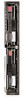
Top View (with access cover and airflow guide removed), Top View of the Server Blade
 |
View all HP Integrity BL60p manuals
Add to My Manuals
Save this manual to your list of manuals |
Page 20 highlights
Introduction Server Blade Components Top View (with access cover and airflow guide removed) There is one removable access cover located on the right side of the server blade. This cover gives access to three printed circuit assemblies (PCAs). See Figure 1-5 for their location: • SCSI backplane • PDH module • Communications module Figure 1-5 Top View of the Server Blade Fan assembly Power pod 0 Power pod 1 Processor 0 Processor 1 Front of Server SCSI backplane PDH module Memory DIMMs Communications module The following field replaceable components (FRUs) are also accessible when the access cover is removed: • Fan assembly (four fans in a plastic assembly bracket) • Processors • Memory DIMMs None of these items are hot-swappable. They are only accessible when the server blade is removed from the enclosure. 20 Chapter 1
-
 1
1 -
2
-
3
-
4
-
5
-
6
-
7
-
8
-
9
-
10
-
11
-
12
-
13
-
14
-
 15
15 -
 16
16 -
 17
17 -
 18
18 -
 19
19 -
 20
20 -
 21
21 -
 22
22 -
 23
23 -
 24
24 -
 25
25 -
26
-
27
-
28
-
29
-
30
-
31
-
32
-
33
-
34
-
35
-
36
-
37
-
38
-
39
-
40
-
41
-
42
-
43
-
44
-
45
-
46
-
47
-
48
-
49
-
50
-
51
-
52
-
53
-
54
-
55
-
56
-
57
-
58
-
59
-
60
-
61
-
62
-
63
-
64
-
65
-
66
-
67
-
68
-
69
-
70
-
71
-
72
-
73
-
74
-
75
-
76
-
77
-
78
-
79
-
80
-
81
-
82
-
83
-
84
-
85
-
86
-
87
-
88
-
89
-
90
 |
 |
