HP Integrity rx5670 CPU Installation Product Update - Page 4
Pin Alignment Aids
 |
View all HP Integrity rx5670 manuals
Add to My Manuals
Save this manual to your list of manuals |
Page 4 highlights
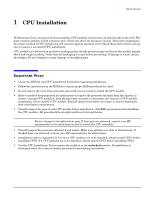
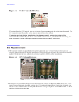
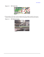
CPU Installation Pin Alignment Aids Figure 1-1 Socket - Unlocked Position camlocked When installing the CPU module, use care to insert all processor pins into the socket simultaneously. The two connectors must be parallel as the pins are inserted in to the sockets. When pins are bent during installation, the damage usually occurs at a corner of the connector. Do not allow the pins at one corner of the connectors to be joined before the remaining pins enter the socket. Careful handling is required to protect the pins during installation. Pin Alignment Aids 1. The processor sockets on extender boards include alignment tabs to ensure that processor pins are correctly aligned during CPU module installation. These tabs fit into cutouts in the connector on the CPU module. Check that the tabs and cutouts are intact and free of debris before installation. Figure 1-2 CPU Tabs and Cutouts contabs 2. Guide pins are provided on the processor extender board to assist in alignment. While these pins do not assure precise alignment, they will position the CPU module for installation. Check that the guide pins intact and free of debris before starting. Check that the corresponding holes in the CPU module are clean and free of debris before starting. 4 Chapter 1
-
 1
1 -
 2
2 -
 3
3 -
 4
4 -
 5
5 -
 6
6
 |
 |
