HP Kayak XU800 hp kayak xu800, technical reference manual - Page 138
USB Stacked Connector, Serial Port A top and, Serial Port B bottom, Connectors
 |
View all HP Kayak XU800 manuals
Add to My Manuals
Save this manual to your list of manuals |
Page 138 highlights
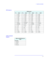
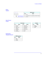
7 Connectors and Sockets Rear Panel Socket Pin Layouts USB Stacked Connector The below USB graphic and pinout table is for a USB connector. However, the information is also valid for a USB Stacked Connector. 1 23 4 USB Stacked Connector Pin Signal 1 VBus 2 D3 D+ 4 GND Shell Shield Serial Port A (top) and Serial Port B (bottom) Connectors Even though the below graphic and pinout table is for one connector, the information is valid for both the Serial Port A and Serial Port B Connectors. 1 6 2 7 3 8 4 9 5 9-pin Serial Port Connector Pin Signal Pin Signal 6 (DSR) CC 7 (RTS) CA 8 (CTS) CB 9 (R) CE 1 (DCD) CF 2 (RD) BB 3 (TD) BA 4 (DTR) CD 5 (GND) AB 138
-
 1
1 -
2
-
3
-
4
-
5
-
6
-
7
-
8
-
9
-
10
-
11
-
12
-
13
-
14
-
15
-
16
-
17
-
18
-
19
-
20
-
21
-
22
-
23
-
24
-
25
-
26
-
27
-
28
-
29
-
30
-
31
-
32
-
33
-
34
-
35
-
36
-
37
-
38
-
39
-
40
-
41
-
42
-
43
-
44
-
45
-
46
-
47
-
48
-
49
-
50
-
51
-
52
-
53
-
54
-
55
-
56
-
57
-
58
-
59
-
60
-
61
-
62
-
63
-
64
-
65
-
66
-
67
-
68
-
69
-
70
-
71
-
72
-
73
-
74
-
75
-
76
-
77
-
78
-
79
-
80
-
81
-
82
-
83
-
84
-
85
-
86
-
87
-
88
-
89
-
90
-
91
-
92
-
93
-
94
-
95
-
96
-
97
-
98
-
99
-
100
-
101
-
102
-
103
-
104
-
105
-
106
-
107
-
108
-
109
-
110
-
111
-
112
-
113
-
114
-
115
-
116
-
117
-
118
-
119
-
120
-
121
-
122
-
123
-
124
-
125
-
126
-
127
-
128
-
129
-
130
-
131
-
132
-
 133
133 -
 134
134 -
 135
135 -
 136
136 -
 137
137 -
 138
138 -
 139
139 -
 140
140
 |
 |
138
7
Connectors and Sockets
Rear Panel Socket Pin Layouts
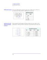
USB Stacked Connector
The below USB graphic and pinout table is for a USB connector. However,
the information is also valid for a USB Stacked Connector.
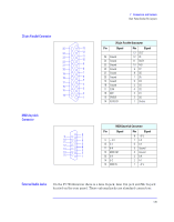
Serial Port A (top) and
Serial Port B (bottom)
Connectors
Even though the below graphic and pinout table is for one connector, the
information is valid for both the Serial Port A and Serial Port B Connectors.
USB Stacked Connector
Pin
Signal
1
VBus
2
D-
3
D+
4
GND
Shell
Shield
1
2
3
4
1
2
3
4
5
6
7
8
9
9-pin Serial Port Connector
Pin
Signal
Pin
Signal
1
(DCD) CF
6
(DSR) CC
2
(RD) BB
7
(RTS) CA
3
(TD) BA
8
(CTS) CB
4
(DTR) CD
9
(R) CE
5
(GND) AB