HP LH4r HP IA-32 Server Long Distance Cluster Interconnect for Windows Phase 1
HP LH4r - NetServer - 256 MB RAM Manual
 |
View all HP LH4r manuals
Add to My Manuals
Save this manual to your list of manuals |
HP LH4r manual content summary:
- HP LH4r | HP IA-32 Server Long Distance Cluster Interconnect for Windows Phase 1 - Page 1
paper that can be found on HP's IA-32 server Reference Material web site at: http://netserver.hp.com/products/high_availability/ms_white_papers.asp. . For more details on the specific storage configurations tested, reference the 'manuals' section of http://www.hp.com/support/clxxp. One of the main - HP LH4r | HP IA-32 Server Long Distance Cluster Interconnect for Windows Phase 1 - Page 2
heartbeat ping, the cluster service will begin failover procedures including ownership arbitration for resources and applications owned by the failed server. Failure to respond to table details cluster interconnect components and specifications associated with three defined distance ranges - HP LH4r | HP IA-32 Server Long Distance Cluster Interconnect for Windows Phase 1 - Page 3
to other high-speed LAN technologies, but the software while also supporting integrated into existing Ethernet and Fast Ethernet networks. In contrast, other high-speed technologies use fundamentally different frame formats. According to the current Gigabit Ethernet specifications of servers - HP LH4r | HP IA-32 Server Long Distance Cluster Interconnect for Windows Phase 1 - Page 4
supports FDDI PCI adapters for future implementations. • VIA was primarily targeted for use in high performance inter-server . Hardware components • HP Netserver LPr servers as cluster nodes with Software components • Cluster servers: Windows NT 4.0 Server EE, SP6a or Windows 2000 Advanced Server - HP LH4r | HP IA-32 Server Long Distance Cluster Interconnect for Windows Phase 1 - Page 5
did not participate in the heartbeat link. The cluster interconnect and public network were totally isolated by using separate VLANs configured on HP ProCurve 8000M Ethernet Switches. In addition to a monitor client, the public part of the network contained a domain controller and eight clients as - HP LH4r | HP IA-32 Server Long Distance Cluster Interconnect for Windows Phase 1 - Page 6
enhancements have not yet been tested and so are not currently supported. Network interface cards in the cluster nodes that are dedicated to paper that can be found on HP's IA-32 server Reference Material web site at: http://netserver.hp.com/products/high_availability/ms_white_papers.asp. summary - HP LH4r | HP IA-32 Server Long Distance Cluster Interconnect for Windows Phase 1 - Page 7
org/internet 6. Internetworking Troubleshooting Handbook, http://www.ciscopress.com 7. HP ProCurve Switches 1600M, 2424M, 4000M, and 8000M, Management and Configuration Guide, http://www.hp.com/go/network_city 8. Advanced Servers Clusters, http://netserver.hp.com/netserver/products/ha_techpapers.asp
-
 1
1 -
 2
2 -
 3
3 -
 4
4 -
 5
5 -
 6
6 -
 7
7
 |
 |

hp ia-32 server
april 2001
technical white
paper
HP IA-32 Server Long Distance Cluster Interconnect for Windows
Phase 1: up to 500m
executive summary
The goals for the Long Distance Cluster Interconnect project are to investigate, select and evaluate technologies that are appropriate
to extend distances for the Microsoft cluster interconnect within the Windows 2000 operating environment. Cluster interconnect in
this document applies to the dedicated private network in the Microsoft Cluster Server (MSCS) cluster also known as heartbeat link.
The project has been divided into three phases associated with the following ranges of distances between cluster nodes:
•
Phase One:
Up to 500m
•
Phase Two:
Up to 10Km
•
Phase Three:
Over 10Km
This white paper documents the first phase of the project.
Phases Two and Three of this project were tested in HP’s Lab and
documented in the ‘HP IA-32 Server Long Distance Cluster Interconnect for Windows, Phases 2 and 3: up to 10Km and over’ white
paper that can be found on HP’s IA-32 server Reference Material web site at:
.
overview
This paper documents the first phase of extending heartbeat link distances.
Stretching the dedicated private network is one
component to achieving resilience in the event of a disaster.
The other necessary component is stretching the storage component.
HP has accomplished this by multiplexing the IP traffic over the same long haul interconnect that the storage traffic uses.
For more
details on the specific storage configurations tested, reference the ‘manuals’ section of
.
One of the main requirements for all ranges of heartbeat link distances is to use fiber-optic cable as the data transportation media.
To analyze this and other requirements several existing communication technologies such as Fiber Distributed Data Interface (FDDI),
Ethernet, Fast Ethernet, Gigabit Ethernet, and Virtual Interface Architecture (VIA) are discussed.
The following subsections describe and compare those currently existing communication technologies eligible to satisfy the goals of
the first phase of the Long Distance Cluster Interconnect project.
Others are discussed in the white paper covering Phases Two and
Three, such as Asynchronous Transfer Mode (ATM) and Dense Waveform Division Multiplexing (DWDM) that could be appropriate
to use for fiber optic communications with longer distances. Gigabit Ethernet (GbE) will also be considered as a technology to be
used to achieve the project goals.
Understanding the importance of having a highly reliable and available cluster interconnect is essential to the proper selection of a
communication technology that will serve as a long distance link.
Cluster Interconnect
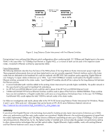
Each cluster node periodically broadcasts network messages across the cluster interconnect to keep other nodes informed of its
health and configuration. The heartbeat signal is sent over a private network used for inter-node communications only. The cluster
interconnect is formed by installing network cards in each node and connecting them by an appropriate network cable. The link
must be configured using the TCP/IP protocol and must be isolated from the public network by a different IP subnet. A generic 2-
node cluster configuration is shown in Figure 1.
1