HP LH4r HP Netserver LC 3 Installation Roadmap - Page 3
Set Up NetServer, Prepare for Hardware Installation, Remove the Covers
 |
View all HP LH4r manuals
Add to My Manuals
Save this manual to your list of manuals |
Page 3 highlights
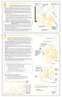
3 Set Up NetServer 1. Mount the HP NetServer on the pedestal. However, if you plan to install the HP NetServer in a rack assembly, wait until after you install all optional accessories and replace covers. ! The instructions molded into the pedestal point toward the front of the pedestal and show the centerline. ! Use them to center the HP NetServer so its front extends 2 inches (5 cm) beyond the front of the pedestal. ! Then push the HP NetServer in toward the rear of the pedestal until it locks into place. See illustration at right. 2. Connect cables: Connect the monitor, keyboard, and mouse to the HP NetServer, and plug in the power cords to the HP NetServer and to the monitor. 3. Connect Optional Uninterruptible Power Supply (UPS). Refer to the instructions supplied with the UPS if you have one. Rear View Mouse Connector Keyboard Connector Monitor Connector Power Connector Pedestal 4 Prepare for Hardware Installation NOTE Two different CD-ROMs are shipped with the system. Make sure you have selected the CD-ROM that includes HP NetServer Navigator. 1. Boot the HP Navigator CD-ROM: Turn on the monitor. Poweron the HP NetServer, and eject the CD-ROM drive. Place the HP Navigator CD-ROM in the drive, and close the drive. Turn off the NetServer power, wait 10 seconds, and turn on the power again. If the system fails to boot, follow the instructions on the screen. When HP Navigator starts, you can change its language, set the time and date, and change the BIOS language. 2. View the Readme file: Select "Readme File" from the HP Navigator Main Menu. The Readme file contains the latest information to help you install your HP NetServer. 3. Run Diagnostic Assistant (optional): To verify the HP NetServer hardware as shipped, run Diagnostic Assistant from the HP Navigator CD-ROM. Select "NetServer Utilities" from the HP Navigator Main Menu, and then select "Diagnostic Assistant" from the NetServer Utilities menu. 4. Install Information Assistant: Information Assistant (IA) is a set of online documentation for the HP NetServer. IA provides information to help install your NetServer. It is easier to use from another system, rather than the one you are installing. Install Information Assistant onto the client system that you use to manage your HP NetServer. To do so, insert the HP NetServer Online Documentation CD-ROM, run Windows. From the Program Manager, select the file menu, choose run, and enter drive:\infoasst\setup where "drive" is the letter of the CD drive. 5. Visit Order Assistant (optional) on the Internet at http://www.hp.com/netserver. Order Assistant lists HP and third-party components that have been tested and found to work with your HP NetServer. It also lists HP accessories, cables, and connectors for your HP NetServer. 6. Obtain IntranetWare key (optional): If you plan to install the optional IntranetWare software that came with your HP NetServer, purchase the software and obtain the key before beginning NOS installation in Step 11: "Configure the HP NetServer." Use the key request form in the HP NetServer Software Option Package. 5 Remove the Covers To prepare to install memory, accessories, and boards, do the following: ! Turn off the NetServer and disconnect the power cord. ! Remove the front bezel and top cover. ! If you are installing accessory boards or a non-hot-swap mass storage device, also remove one side cover. To install some options, you will need a flat 1/4-inch screwdriver and T15 TORX® driver. WARNING Before removing the cover, disconnect the power cord and unplug telephone cables. Disconnect the power cord to cut standby power and reduce shock hazards. Disconnect telephone cables to eliminate shock hazard from telephone ringing voltages. 1. Unlock the front bezel key lock with the key in the key bag located on the rear of the HP NetServer. Remove the front bezel by pulling on the pocket in the side of the bezel to swing that side outward, and then pull the bezel off. 2. Remove the top cover: Loosen both thumbscrews. Pull the front of the top cover forward 1/16 inch (1.5 mm). 3. Lift the front of the top cover up enough to create a gap of 1 inch (3 cm), but no more, between the front of the top cover and the top of the chassis. Push the top cover back, and lift it off. Front Bezel Pocket Key Lock 1 Thumbscrews Unlocked Position Top Cover 1 inch (3 cm) System Board 2 Tabs CAUTION Lifting the top cover higher than 1 inch (3 cm) can damage it and the chassis. 3 4. Remove the side cover, if needed: On the side cover farthest from the system board, grasp the two tabs at the top of the cover, pull upward and outward, and lift the cover off. CAUTION Wear a wrist strap and use a staticdissipating work surface connected to the chassis when handling components. Side 4 Cover
-
 1
1 -
 2
2 -
 3
3 -
 4
4 -
 5
5 -
 6
6
 |
 |
