HP LH4r HP Netserver LH 6000 Technical Reference Card - Page 2
Cabling: Power, Cabling: Data, I/O Board, Hot-Swap Mass Storage Configurations
 |
View all HP LH4r manuals
Add to My Manuals
Save this manual to your list of manuals |
Page 2 highlights
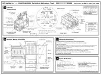
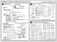
HP NetServer LH 6000 / LH 6000r Technical Reference Card HP Product No. D9103-80201, Feb. 2000 E Cabling: Power Front Panel Display Cable P/O Display Flexible Disk Drive IDE CD-ROM To rear panel Management Port Power Management/Interconnection Board To rear panel OLx board Cable P/O Panel To Optional Mass Storage Device Primary Hot-Swap Mass Storage Cage SCSI A Secondary (Optional) Hot-Swap Mass Storage Cage SCSI B F I/O Board Remote Management OLx Connector PCI Slots 1-6: +5V, 33 MHz, 32- or 64 Bit I/O Memory (for NetRAID 32MB, 64MB or 128MB Cache) Non-Hot-Plug Slots (1 - 4) SE SCSI Connector I/O Fan (Removed) 1 Card Retainer and Lever 2 (1 of 8) 3 Blind Mate Fan Connector Location of 4 OLx Board 5 PCI Slots 7, 8: +3.3V or 6 Universal,* 33/66 MHz, 7 32- or 64-Bit 8 PCI Slot Separator SCSI A Connector SCSI B Connector I/O Fan Attention LED (Amber) Hot-Plug Slots (5 - 8) PCI Slot Separator (1 of 4) Power LED (Green) * A "Universal Card" accepts either 3.3V or 5V and is keyed to fit slots 7 & 8. I/O Board Cabling: Data To Non Hot-Swap 4W Mass Storage 4W 14W IDE CD-ROM Flexible Disk Drive 2W To Secondary (Optional) Hot-Swap Mass Storage Cage Power Supply Redundant Power Supply = on backside of Pwr Mgmnt/Intercnct PCI Attention LEDs (Hot-Swap) To OLx Connector (I/O board) To Management Port Connector (I/O Board) Power Supply Control Cable 4 3 2 1 Power Management/Interconnection Board To Primary Hot-Swap 14W Mass Storage Cage PS1 PS2 PS3 PS4 Rear of Unit G Hot-Swap Mass Storage Configurations • Ensure Hot-Swap drives are installed in lowest or left-most slot first. Duplex SCSI Addressing (One Cage) AB AB AB • Use SCSI A only for Primary Cage, SCSI B only 2 2 2 for Secondary Cage. 1 1 • For duplex configurations, install duplex board and reconfigure as shown in the 3 diagrams at 0 0 0 right. 2 2 2 • Pedestal configurations are shown here. For Rack configurations, rotate diagrams 90º clockwise. 1 • All 1.6˝ Drives require the use of a .5˝ Drive Spacer. 0 0 0 Simplex SCSI Addressing (One Cage) 6 LP HH, LP, HH, LP 1 HH, 4 LP SCSI A A A A A A 9 9 9 9 9 8 8 8 8 8 3 3 2 2 2 2 2 2 2 1 1 0 0 0 0 0 0 6 LP 3 HH 1 HH, 4 LP 2 LP, HH, 2 LP HH, LP Alt. 2 HH, 2 LP Key 1.6˝ Half-Height (HH) Drive 1˝ Low-Profile (LP) Drive .5˝ Drive Spacer For additional information, see other side.
-
 1
1 -
 2
2
 |
 |
