HP LH4r HP Netserver LXe Pro Installation Road Map - Page 5
Install Additional PCI Boards and EISA Boards, Install Additional Mass Storage Devices
 |
View all HP LH4r manuals
Add to My Manuals
Save this manual to your list of manuals |
Page 5 highlights
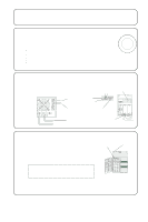
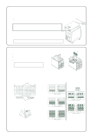
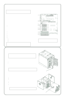
7 Install Additional PCI Boards and EISA Boards NOTE Do not install ISA boards until instructed to do so by the Configuration Assistant program in Step 10 of this Road Map. Installation Instructions Memory Board 1. Read the documentation that is included with each board. Note any special instructions and refer to the Installation Recommendations. See the Service Reference Label for additional requirements. 2. For full-length boards, remove the PCI/EISA board retainer. 3. Remove the slot cover for each slot used. 4. Insert the board in the desired slot. Consider the boot order when selecting a slot. Accessory Board Installation Recommendations ! For a list of boards that HP has tested, refer to the HP NetServer Navigator CD-ROM. Also refer to the Readme file for the latest configuration information. Boot Device Priority Order The system will search for a bootable device in the following order: ! CD-ROM drive with bootable CD-ROM (must be enabled by the EISA configuration utility) ! Flexible disk drive with bootable flexible disk (must be enabled by the EISA Configuration Utility) ! IDE drive (must be enabled by the EISA Configuration Utility) ! EISA or ISA controller in the EISA/ISA bus slots in the following order: ! E1/E2/E3/E4 ! PCI controller ! PCI bus slots in this order: P1/P2/P3/P4 ! Embedded SCSI A controller ! Embedded SCSI B controller ! PCI bus slots in the following order: P5/P6 Processor Modules #2 #1 PCI Bus 0 P1 P2 P3 PCI Bus 1 P4 P5 P6 EISA/ISA Bus E1 E2 E3 E4 NOTE You can change the PCI boot priority so that the embedded SCSI controllers will precede the PCI bus slots. To do so, open the EISA Configuration Utility and enable the option called "Boot from Embedded SCSI." CAUTION Do not install a second processor board unless a minimum of two power supply modules are installed. 8 Install Additional Mass Storage Devices NOTE When you install an IDE driver or SCSI devices in certain configurations, you may require special cables or adapters. See the Service Reference Label under the top cover or Information Assistant on the HP Navigator CD-ROM for special configuration instructions. Hot Swap Subsystem ! All devices must be installed in hot swap mass storage trays. Be sure to remove any shipping plugs from all hot swap devices before you install them. ! To view cabling configuration diagrams and power supply requirements for this subsystem, refer to the Service Reference Label beneath the top cover or to the corresponding topic in the Information Assistant on the HP NetServer Navigator CD-ROM. NOTE Users who have Ultra SCSI in their systems should refer to the appropriate section in the HP NetServer LX Pro Series User Guide for additional information. Remove Shipping Plugs from Hot Swap Drives Upper Shelves ! The front bezel must be removed before you install mass storage devices. ! Remove both side covers (1) and (2) before removing the front bezel (3). ! All devices must be installed in mass storage trays, which are ordered separately. For part numbers, refer to the Product Reference Label on the side of the chassis. ! You can install SCSI, IDE or flexible disk drives on the upper shelves. ! If you install a 50-pin, narrow SCSI device, it can be cabled with the CD- ROM. (1) ! If you are installing a SCSI device, set its jumpers to an unused address (note that the CD-ROM drive is set to SCSI address 5). CAUTION Do not install any mass storage devices in the right side unless the system has at least two power supply modules installed. SCSI Device Installation (2) (3)
-
 1
1 -
 2
2 -
 3
3 -
 4
4 -
 5
5 -
 6
6
 |
 |
