HP LP2065 An Overview of Current Display Interfaces - Page 5
Table 1 VGA Connector Pinout, Signal
 |
UPC - 882780206175
View all HP LP2065 manuals
Add to My Manuals
Save this manual to your list of manuals |
Page 5 highlights
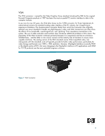
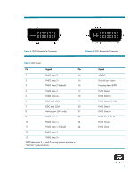
Figure 2 VGA Connector Pinout Table 1 VGA Connector Pinout Pin Signal 1 Red video 2 Green video 3 Blue video 4 Unused (n.c.) 5 Return 6 Red return 7 Green return 8 Blue return 9 +5 VDC 10 Sync. return 11 Unused 12 DDC Data (SDA) 13 Horizontal sync (TTL) 14 Vertical sync (TTL) 15 DDC Clock (SCL) 5
-
 1
1 -
 2
2 -
 3
3 -
 4
4 -
 5
5 -
 6
6 -
 7
7 -
 8
8 -
 9
9 -
 10
10 -
 11
11 -
12
-
13
-
14
 |
 |

5
Figure 2
VGA Connector Pinout
Table 1
VGA Connector Pinout
Pin
Signal
1
Red video
2
Green video
3
Blue video
4
Unused (n.c.)
5
Return
6
Red return
7
Green return
8
Blue return
9
+5 VDC
10
Sync. return
11
Unused
12
DDC Data (SDA)
13
Horizontal sync (TTL)
14
Vertical sync (TTL)
15
DDC Clock (SCL)