HP LTE Notebook PC 5150 LTE 5000 Family of Personal Computers Maintenance and - Page 193
Bottom Cover Assembly, 4.2 MPEG Connector Door
 |
View all HP LTE Notebook PC 5150 manuals
Add to My Manuals
Save this manual to your list of manuals |
Page 193 highlights
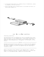
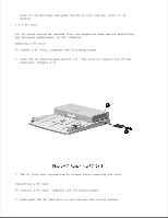
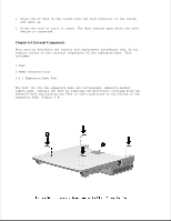
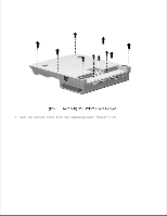
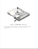
6.4.2 MPEG Connector Door The MPEG connector door [2] provides visual access to the MPEG connector for guiding the connector into place when installing the bottom cover assembly with the connector attached to the bottom cover (Figure 6-8). Procedures presented later in this manual prescribe separating the MPEG connector from the bottom cover at disassembly and not removing the MPEG connector door. If you choose to leave the MPEG connector attached to the bottom cover, you should remove the MPEG connector door for visual access to the MPEG connector and its connecting location on the main board. Use a small flat-blade screwdriver to pry the MPEG connector door loose. Chapter 6.5 Bottom Cover Assembly The bottom cover assembly is spared as a unit and consists of: o Bottom cover o MPEG connector access door o Feet o Labels The feet are also spared separately. Feet installation is described in Section 6.4.2. The feet, labels, and MPEG connector access door are preinstalled. To remove the bottom cover assembly, complete the following steps: 1. Prepare the expansion base for disassembly as described in Section 6.3. 2. Place the expansion base face down on the work surface and remove the ten screws that secure the bottom cover to the expansion base (Figure 6-9).
-
 1
1 -
2
-
3
-
4
-
5
-
6
-
7
-
8
-
9
-
10
-
11
-
12
-
13
-
14
-
15
-
16
-
17
-
18
-
19
-
20
-
21
-
22
-
23
-
24
-
25
-
26
-
27
-
28
-
29
-
30
-
31
-
32
-
33
-
34
-
35
-
36
-
37
-
38
-
39
-
40
-
41
-
42
-
43
-
44
-
45
-
46
-
47
-
48
-
49
-
50
-
51
-
52
-
53
-
54
-
55
-
56
-
57
-
58
-
59
-
60
-
61
-
62
-
63
-
64
-
65
-
66
-
67
-
68
-
69
-
70
-
71
-
72
-
73
-
74
-
75
-
76
-
77
-
78
-
79
-
80
-
81
-
82
-
83
-
84
-
85
-
86
-
87
-
88
-
89
-
90
-
91
-
92
-
93
-
94
-
95
-
96
-
97
-
98
-
99
-
100
-
101
-
102
-
103
-
104
-
105
-
106
-
107
-
108
-
109
-
110
-
111
-
112
-
113
-
114
-
115
-
116
-
117
-
118
-
119
-
120
-
121
-
122
-
123
-
124
-
125
-
126
-
127
-
128
-
129
-
130
-
131
-
132
-
133
-
134
-
135
-
136
-
137
-
138
-
139
-
140
-
141
-
142
-
143
-
144
-
145
-
146
-
147
-
148
-
149
-
150
-
151
-
152
-
153
-
154
-
155
-
156
-
157
-
158
-
159
-
160
-
161
-
162
-
163
-
164
-
165
-
166
-
167
-
168
-
169
-
170
-
171
-
172
-
173
-
174
-
175
-
176
-
177
-
178
-
179
-
180
-
181
-
182
-
183
-
184
-
185
-
186
-
187
-
 188
188 -
 189
189 -
 190
190 -
 191
191 -
 192
192 -
 193
193 -
 194
194 -
 195
195 -
 196
196 -
 197
197 -
 198
198 -
199
-
200
-
201
-
202
-
203
-
204
-
205
-
206
-
207
-
208
-
209
-
210
-
211
-
212
-
213
-
214
-
215
-
216
-
217
-
218
-
219
-
220
-
221
-
222
-
223
-
224
-
225
-
226
-
227
-
228
-
229
-
230
-
231
-
232
-
233
-
234
-
235
-
236
-
237
-
238
-
239
-
240
-
241
-
242
-
243
-
244
-
245
-
246
-
247
-
248
-
249
-
250
-
251
-
252
-
253
-
254
-
255
-
256
-
257
-
258
-
259
-
260
-
261
-
262
-
263
-
264
-
265
-
266
-
267
-
268
-
269
-
270
-
271
-
272
-
273
-
274
-
275
-
276
-
277
-
278
-
279
-
280
-
281
-
282
-
283
-
284
-
285
-
286
-
287
-
288
-
289
-
290
-
291
-
292
-
293
-
294
-
295
-
296
-
297
-
298
-
299
-
300
-
301
-
302
-
303
-
304
-
305
-
306
-
307
-
308
-
309
-
310
-
311
-
312
-
313
-
314
 |
 |
