HP LaserJet 6L Service Manual - Page 100
Pickup Roller Assembly
 |
View all HP LaserJet 6L manuals
Add to My Manuals
Save this manual to your list of manuals |
Page 100 highlights
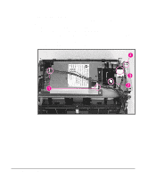
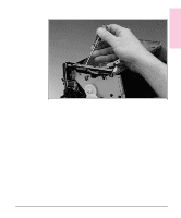
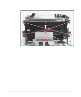
Removal and 6 Replacement Note Figure 6-23 Pickup Roller Assembly 1 Remove the Printer Covers. 2 Remove the paper pickup gear (Figure 6-21). This gear is keyed to go on the shaft in only one way. 3 Remove the pickup roller grounding clip on the right of the printer by lifting each end of the clip up and over the two metal guides and sliding the clip off. Figure 6-23 depicts the clip from an HP LaserJet 5L. The clip from an HP LaserJet 6L (and some HP LaserJet 5Ls) is shaped differently. Pickup Roller Assembly Removal (1 of 2) Removal and Replacement 6 - 27
-
 1
1 -
2
-
3
-
4
-
5
-
6
-
7
-
8
-
9
-
10
-
11
-
12
-
13
-
14
-
15
-
16
-
17
-
18
-
19
-
20
-
21
-
22
-
23
-
24
-
25
-
26
-
27
-
28
-
29
-
30
-
31
-
32
-
33
-
34
-
35
-
36
-
37
-
38
-
39
-
40
-
41
-
42
-
43
-
44
-
45
-
46
-
47
-
48
-
49
-
50
-
51
-
52
-
53
-
54
-
55
-
56
-
57
-
58
-
59
-
60
-
61
-
62
-
63
-
64
-
65
-
66
-
67
-
68
-
69
-
70
-
71
-
72
-
73
-
74
-
75
-
76
-
77
-
78
-
79
-
80
-
81
-
82
-
83
-
84
-
85
-
86
-
87
-
88
-
89
-
90
-
91
-
92
-
93
-
94
-
 95
95 -
 96
96 -
 97
97 -
 98
98 -
 99
99 -
 100
100 -
 101
101 -
 102
102 -
 103
103 -
 104
104 -
 105
105 -
106
-
107
-
108
-
109
-
110
-
111
-
112
-
113
-
114
-
115
-
116
-
117
-
118
-
119
-
120
-
121
-
122
-
123
-
124
-
125
-
126
-
127
-
128
-
129
-
130
-
131
-
132
-
133
-
134
-
135
-
136
-
137
-
138
-
139
-
140
-
141
-
142
-
143
-
144
-
145
-
146
-
147
-
148
-
149
-
150
-
151
-
152
-
153
-
154
-
155
-
156
-
157
-
158
-
159
-
160
-
161
-
162
-
163
-
164
-
165
-
166
-
167
-
168
-
169
-
170
-
171
-
172
-
173
-
174
-
175
-
176
-
177
-
178
-
179
-
180
-
181
-
182
-
183
-
184
-
185
-
186
-
187
-
188
-
189
-
190
-
191
-
192
-
193
-
194
-
195
-
196
-
197
-
198
-
199
-
200
-
201
-
202
-
203
-
204
 |
 |

Pickup Roller Assembly
1
Remove the Printer Covers.
2
Remove the paper pickup gear (Figure 6-21).
Note
This gear is keyed to go on the shaft in only one way.
3
Remove the pickup roller grounding clip on the right of the printer by lifting each
end of the clip up and over the two metal guides and sliding the clip off. Figure 6-23
depicts the clip from an HP LaserJet 5L. The clip from an HP LaserJet 6L (and
some HP LaserJet 5Ls) is shaped differently.
Pickup Roller Assembly Removal (1 of 2)
Figure 6-23
6
Removal and
Replacement
Removal and Replacement
6 - 27