HP LaserJet Pro P1600 HP LaserJet Professional P1560 and P1600 Series Printer - Page 93
Reinstallation tip, Remove the pickup assembly 6 of 10
 |
View all HP LaserJet Pro P1600 manuals
Add to My Manuals
Save this manual to your list of manuals |
Page 93 highlights
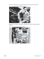
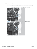
6. Disconnect three connectors (callout 1), and then remove the wire harness (callout 2) from the guide (callout 3). Reinstallation tip When the pickup assembly is reinstalled, place these wire harnesses in the guide first, and then the wire harness from the ground connector in the previous step. This ensures that the harnesses are long enough for the connectors to reach the engine controller PCA. Figure 2-56 Remove the pickup assembly (6 of 10) 2 3 1 7. Remove one bushing (callout 1). Figure 2-57 Remove the pickup assembly (7 of 10) ENWW 1 Main assemblies 75
-
 1
1 -
2
-
3
-
4
-
5
-
6
-
7
-
8
-
9
-
10
-
11
-
12
-
13
-
14
-
15
-
16
-
17
-
18
-
19
-
20
-
21
-
22
-
23
-
24
-
25
-
26
-
27
-
28
-
29
-
30
-
31
-
32
-
33
-
34
-
35
-
36
-
37
-
38
-
39
-
40
-
41
-
42
-
43
-
44
-
45
-
46
-
47
-
48
-
49
-
50
-
51
-
52
-
53
-
54
-
55
-
56
-
57
-
58
-
59
-
60
-
61
-
62
-
63
-
64
-
65
-
66
-
67
-
68
-
69
-
70
-
71
-
72
-
73
-
74
-
75
-
76
-
77
-
78
-
79
-
80
-
81
-
82
-
83
-
84
-
85
-
86
-
87
-
 88
88 -
 89
89 -
 90
90 -
 91
91 -
 92
92 -
 93
93 -
 94
94 -
 95
95 -
 96
96 -
 97
97 -
 98
98 -
99
-
100
-
101
-
102
-
103
-
104
-
105
-
106
-
107
-
108
-
109
-
110
-
111
-
112
-
113
-
114
-
115
-
116
-
117
-
118
-
119
-
120
-
121
-
122
-
123
-
124
-
125
-
126
-
127
-
128
-
129
-
130
-
131
-
132
-
133
-
134
-
135
-
136
-
137
-
138
-
139
-
140
-
141
-
142
-
143
-
144
-
145
-
146
-
147
-
148
-
149
-
150
-
151
-
152
-
153
-
154
-
155
-
156
-
157
-
158
-
159
-
160
-
161
-
162
-
163
-
164
-
165
-
166
-
167
-
168
-
169
-
170
-
171
-
172
-
173
-
174
-
175
-
176
-
177
-
178
-
179
-
180
-
181
-
182
-
183
-
184
-
185
-
186
-
187
-
188
-
189
-
190
-
191
-
192
-
193
-
194
-
195
-
196
-
197
-
198
-
199
-
200
-
201
-
202
-
203
-
204
-
205
-
206
-
207
-
208
-
209
-
210
-
211
-
212
-
213
-
214
-
215
-
216
-
217
-
218
-
219
-
220
-
221
-
222
-
223
-
224
-
225
-
226
 |
 |

6.
Disconnect three connectors (callout 1), and then remove the wire harness (callout 2) from the
guide (callout 3).
Reinstallation tip
When the pickup assembly is reinstalled, place these wire harnesses in the
guide first, and then the wire harness from the ground connector in the previous step. This ensures
that the harnesses are long enough for the connectors to reach the engine controller PCA.
Figure 2-56
Remove the pickup assembly (6 of 10)
2
3
1
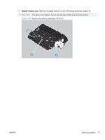
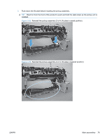
7.
Remove one bushing (callout 1).
Figure 2-57
Remove the pickup assembly (7 of 10)
1
ENWW
Main assemblies
75