HP ML150 HP ProLiant ML 150 G6 Processor Installation Card - Page 1
HP ML150 - ProLiant - G6 Manual
 |
UPC - 884420743644
View all HP ML150 manuals
Add to My Manuals
Save this manual to your list of manuals |
Page 1 highlights
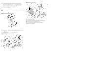
HP ProLiant ML150 G6 Server Processor Option kit Installation Instructions Overview This document contains instructions for installing the optional Processor Option Kit in the HP ProLiant ML150 G6 Server. For more information on preparing the server for installation, refer to the documentation referenced on the HP ProLiant ML150 G6 Server Easy set-up CD . Kit contents • Processor • Processor heat-sink • System fan • Processor Option Kit Document Important safety information Read the installation instructions completely before beginning the installation procedure. Refer to the document titled Important Safety Information on the Easy set-up CD. CAUTION: Electrostatic discharge (ESD) can damage electronic components. Be sure you are properly grounded (earthed) before beginning an installation procedure. Installation guidelines This installation is to be performed by qualified personnel who are knowledgeable of the procedures, precautions, and hazards associated with equipment containing hazardous energy circuits. Figure 1 Chassis layout Legal notices © Copyright 2009 Hewlett-Packard Development Company, L.P. The information contained herein is subject to change without notice. The only warranties for HP products and services are set forth in the express warranty statements accompanying such products and services. Nothing herein should be construed as constituting an additional warranty. HP shall not be liable for technical or editorial errors or omissions contained herein. Part number 530773-001 March 2009 (First Edition) Item Description 1 Power supply unit 2 Processor 1 3 Processor 2 4 System board 5 Air baffle Figure 2 System board Item Description 1 CPU 1 2 CPU 2 3 SYS FAN 1 J54 4 SYS FAN 2 J44 (Redundant) 5 SYS FAN 3 J38 Installing the Processor 1. Back up the server data. 2. Shut down the operating system (OS) in an orderly manner as directed in the OS instructions. 3. If the server is on, press the power button to power down the server. 4. Disconnect the power cord from the system chassis. 5. If necessary, unlock the chassis. 6. Release the rear thumbscrews and remove the access panel. 7. Remove the air baffle by pulling up slightly on the four tabs to release the baffle from the chassis and lift the air baffle away from the system board and chassis. If the heatsink is to be reused, carefully place the heatsink in a position where the base (processor contact area) will not come in contact with foreign matter. Figure 3 Removing the air baffle 8. Place the server on its side with the open side up. 9. Press the load lever, and released from retention tab. 10. Lift the load lever to a 135° angle, and lift load plate to a 100° angle. 11. Remove cover from CPU socket 12. Holding the processor by the edges, insert the processor into the socket(2) Ensure that the processor is correctly positioned with the orientation notch on the socket and that the pins are aligned correctly with the socket holes (Figure 4, 1). 13. Close the retention plate (3) and lower and engage the load lever (4) to fully seat the processor. Figure 4 Installing a processor After you install the processor, the heatsink must be reinstalled on top of the processor socket. The thermal grease applied on the contact surfaces of the processor provides the necessary thermal bonding to allow the heatsink to draw away heat from the processor.
-
 1
1 -
 2
2
 |
 |