HP MSA 1040 HP MSA 1040 Quick Start Instructions (759126-001, March 2014) - Page 4
Step 5. Connect two Remote Snap-capable MSA - san
 |
View all HP MSA 1040 manuals
Add to My Manuals
Save this manual to your list of manuals |
Page 4 highlights
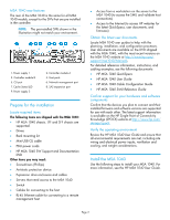
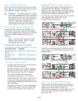
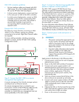
MSA 1040 connection guidelines • No host interface cables are shipped with MSA 1040 arrays. For a list of cables available from HP, see the HP MSA 1040 QuickSpecs. • In direct-connect deployments, connect each host to the same port on both of the MSA controllers. • In switch-connect deployments, connect an MSA Controller A port and the corresponding MSA Controller B port to one switch, and connect a second MSA Controller A port and the corresponding MSA Controller B port to a separate switch. Example MSA 1040 connections The following image illustrates connecting an MSA 1040 FC to two switches, and the two switches connecting to two servers. Eight Fibre Channel cables are required. For more cabling examples, including connecting directly to a server, see the HP MSA 1040 Cabling Configuration Guide. Step 4. Connect the MSA 1040 to a remote management host (optional) A remote management host directly manages systems out-of-band over an Ethernet network. If a remote management host is included in your environment, connect an RJ-45 Ethernet cable from the network management port on each MSA 1040 controller to a switch that your management host can access (preferably on the same subnet). Step 5. Connect two Remote Snap-capable MSA systems to replicate volumes (optional) The MSA 1040 supports HP MSA Remote Snap Software, an optional licensed disaster-recovery utility. This utility performs asynchronous (batch) replication of block-level data from a volume on a primary MSA to a secondary volume on the same system or on a separate, independent MSA system that supports Remote Snap Software. These two MSA systems connect through FC or Ethernet switches that are on the same fabric or network. For more information about Remote Snap Software, including cabling requirements and user information, see the HP MSA 1040 User Guide, HP MSA 1040 SMU Reference Guide, and Remote Snap online help. Step 6. Connect power cords and power on devices IMPORTANT: • The power cord must be approved for use in your country. The power cord must be rated for the product and for the voltage and current marked on the electrical ratings label of the product. • Important safety information about power cords is available in the Safety and Disposal Guide, found on the Software Support/Documentation DVD shipped with the MSA 1040. Apply power to the devices in the following order: 1. Connect power cords from the rack to separate external power sources. 2. Power on the SAN/LAN switches (if necessary). 3. Connect each power supply module in all attached expansion drive enclosures to a power source in the rack. If the drive enclosures have power switches, apply power. If the drive enclosures do not have power switches, they automatically start. 4. Wait one minute to ensure that all drives in the drive enclosure are powered up and ready. 5. Connect each power supply module in the MSA 1040 to a power source in the rack. The MSA 1040 automatically starts (it does not have a power switch). 6. Observe the LEDs on the front and the rear of the MSA 1040 and any expansion drive enclosures, and confirm that no LEDs are amber. 7. Power on the servers (if necessary). Page 4
-
 1
1 -
 2
2 -
 3
3 -
 4
4 -
 5
5
 |
 |