HP Mini 110-3500 HP Mini 110, Compaq Mini CQ10 and HP Mini 1103 - Maintenance - Page 64
Display assembly, Service access cover see
 |
View all HP Mini 110-3500 manuals
Add to My Manuals
Save this manual to your list of manuals |
Page 64 highlights
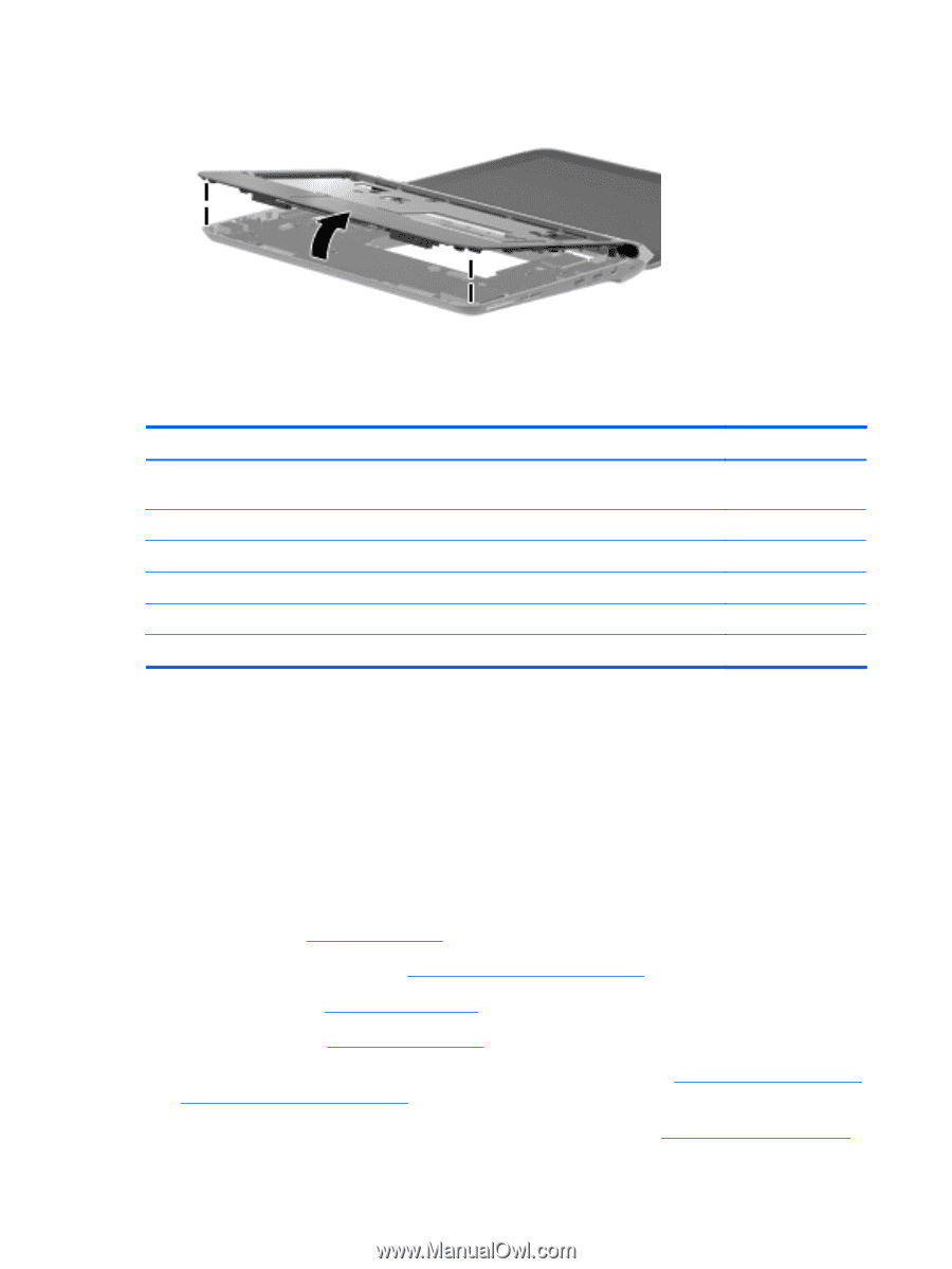
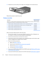
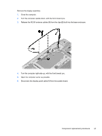
13. Release the top cover by lifting the front edge until it disengages from the base enclosure. Reverse this procedure to install the top cover. Display assembly Description Spare part number 25.7-cm (10.1-in) display assembly (includes display panel cable, 2 WLAN transceivers and cables, 2 WWAN transceivers and cables (select models only), and webcam/microphone module and cable): ● WSVGA, anti-glare, LED display assembly in black for use only on Compaq-branded models 634493-001 ● WSVGA, anti-glare, LED display assembly in black for use only on HP-branded models 633496-001 ● WSVGA, anti-glare, LED display assembly in red 633498-001 ● WSVGA, anti-glare, LED display assembly in blue 633499-001 ● WSVGA, anti-glare, LED display assembly in white 633497-001 Before removing the display assembly, follow these steps: 1. Shut down the computer. If you are unsure whether the computer is off or in Hibernation, turn the computer on, and then shut it down through the operating system. 2. Disconnect all external devices connected to the computer. 3. Disconnect the power from the computer by first unplugging the power cord from the AC outlet and then unplugging the AC adapter from the computer. 4. Remove the following components: a. Battery (see Battery on page 35). b. Service access cover (see Service access cover on page 38). c. Keyboard (see Keyboard on page 50). d. Top cover (see Top cover on page 53). 5. Disconnect the WWAN antenna cables from the WWAN module (see WWAN and GPS modules (select models only) on page 43). 6. Disconnect the WLAN antenna cables from the WLAN module (see WLAN module on page 45). 56 Chapter 4 Removal and replacement procedures
-
 1
1 -
2
-
3
-
4
-
5
-
6
-
7
-
8
-
9
-
10
-
11
-
12
-
13
-
14
-
15
-
16
-
17
-
18
-
19
-
20
-
21
-
22
-
23
-
24
-
25
-
26
-
27
-
28
-
29
-
30
-
31
-
32
-
33
-
34
-
35
-
36
-
37
-
38
-
39
-
40
-
41
-
42
-
43
-
44
-
45
-
46
-
47
-
48
-
49
-
50
-
51
-
52
-
53
-
54
-
55
-
56
-
57
-
58
-
 59
59 -
 60
60 -
 61
61 -
 62
62 -
 63
63 -
 64
64 -
 65
65 -
 66
66 -
 67
67 -
 68
68 -
 69
69 -
70
-
71
-
72
-
73
-
74
-
75
-
76
-
77
-
78
-
79
-
80
-
81
-
82
-
83
-
84
-
85
-
86
-
87
-
88
-
89
-
90
-
91
-
92
-
93
-
94
-
95
-
96
-
97
-
98
-
99
-
100
-
101
 |
 |