HP Mini 110-3700ca HP Mini 110 and Compaq Mini CQ10 - Maintenance and Service - Page 81
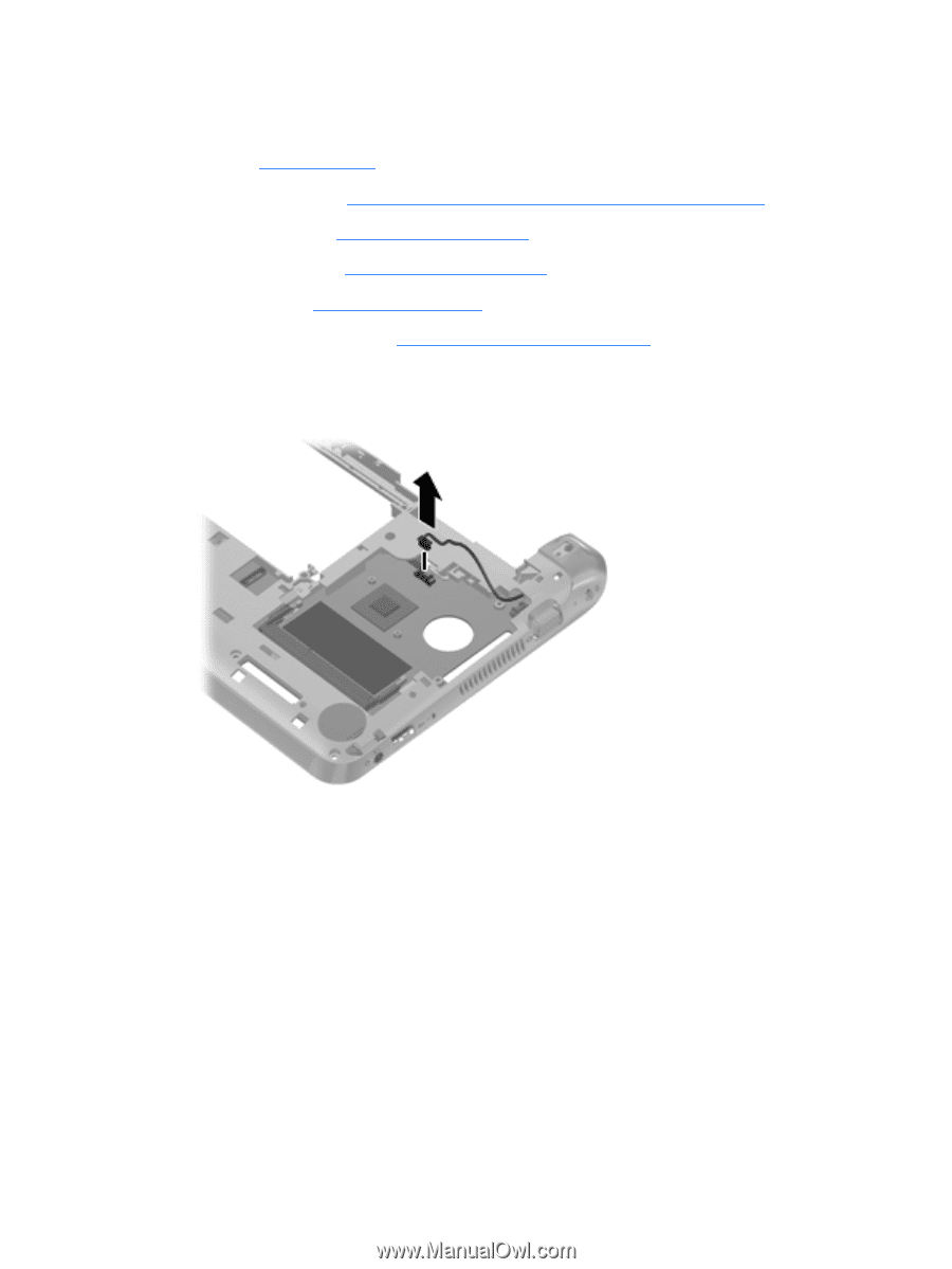
Remove the 2 Phillips 2.0×4.0 screws, Disconnect the power connector cable from the system board.
 |
View all HP Mini 110-3700ca manuals
Add to My Manuals
Save this manual to your list of manuals |
Page 81 highlights
When replacing the system board, be sure that the following components are removed from the defective system board and installed on the replacement system board: ● SIM (see SIM on page 42) ● WWAN module (see WWAN and GPS modules (select models only) on page 48) ● WLAN module (see WLAN module on page 50) ● Memory module (see Memory module on page 52) ● RTC battery (see RTC battery on page 53) ● Fan/heat sink assembly (see Fan/heat sink assembly on page 69) Remove the system board: 1. Disconnect the power connector cable from the system board. 2. Remove the 2 Phillips 2.0×4.0 screws (1) that secure the system board to the base enclosure. 3. Lift the right side of the system board (2) until it rests at an angle. Component replacement procedures 73
-
 1
1 -
2
-
3
-
4
-
5
-
6
-
7
-
8
-
9
-
10
-
11
-
12
-
13
-
14
-
15
-
16
-
17
-
18
-
19
-
20
-
21
-
22
-
23
-
24
-
25
-
26
-
27
-
28
-
29
-
30
-
31
-
32
-
33
-
34
-
35
-
36
-
37
-
38
-
39
-
40
-
41
-
42
-
43
-
44
-
45
-
46
-
47
-
48
-
49
-
50
-
51
-
52
-
53
-
54
-
55
-
56
-
57
-
58
-
59
-
60
-
61
-
62
-
63
-
64
-
65
-
66
-
67
-
68
-
69
-
70
-
71
-
72
-
73
-
74
-
75
-
 76
76 -
 77
77 -
 78
78 -
 79
79 -
 80
80 -
 81
81 -
 82
82 -
 83
83 -
 84
84 -
 85
85 -
 86
86 -
87
-
88
-
89
-
90
-
91
-
92
-
93
-
94
-
95
-
96
-
97
-
98
-
99
-
100
-
101
-
102
-
103
-
104
-
105
-
106
-
107
-
108
 |
 |