HP Mini 210-4000 HP Mini 210, HP Mini 110, Compaq Mini CQ10 - Maintenance and - Page 78
Removal and replacement procedures, base enclosure.
 |
View all HP Mini 210-4000 manuals
Add to My Manuals
Save this manual to your list of manuals |
Page 78 highlights
6. Remove the corner covers. 7. Release the wireless antenna cables from the clips (1) and routing channel built into the base enclosure. 8. Disconnect the display panel cable (2) from the system board. 70 Chapter 4 Removal and replacement procedures
-
 1
1 -
2
-
3
-
4
-
5
-
6
-
7
-
8
-
9
-
10
-
11
-
12
-
13
-
14
-
15
-
16
-
17
-
18
-
19
-
20
-
21
-
22
-
23
-
24
-
25
-
26
-
27
-
28
-
29
-
30
-
31
-
32
-
33
-
34
-
35
-
36
-
37
-
38
-
39
-
40
-
41
-
42
-
43
-
44
-
45
-
46
-
47
-
48
-
49
-
50
-
51
-
52
-
53
-
54
-
55
-
56
-
57
-
58
-
59
-
60
-
61
-
62
-
63
-
64
-
65
-
66
-
67
-
68
-
69
-
70
-
71
-
72
-
 73
73 -
 74
74 -
 75
75 -
 76
76 -
 77
77 -
 78
78 -
 79
79 -
 80
80 -
 81
81 -
 82
82 -
 83
83 -
84
-
85
-
86
-
87
-
88
-
89
-
90
-
91
-
92
-
93
-
94
-
95
-
96
-
97
-
98
-
99
-
100
-
101
-
102
-
103
-
104
-
105
-
106
-
107
-
108
-
109
-
110
-
111
-
112
-
113
-
114
 |
 |
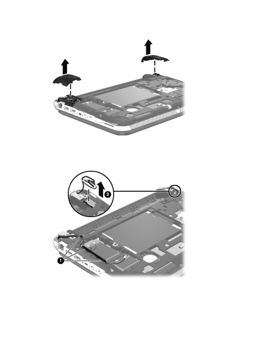
6.
Remove the corner covers.
7.
Release the wireless antenna cables from the clips
(1)
and routing channel built into the
base enclosure.
8.
Disconnect the display panel cable
(2)
from the system board.
70
Chapter 4
Removal and replacement procedures