HP Model 735 hp workstation 9000 series model 735 - service handboook - Page 13
System, Unit Controls
 |
View all HP Model 735 manuals
Add to My Manuals
Save this manual to your list of manuals |
Page 13 highlights
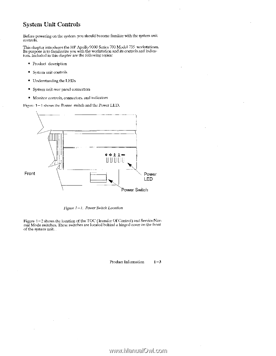
System Unit Controls Before powering on the system, you should become familiar with the system unit controls. This chapter introduces the HP Apollo 9000 Series 700 Model 735 workstations. Its purpose is to familiarize you with the workstation and its controls and indicators. Included in this chapter are the following topics: q Product description q System unit controls q Understanding the LEDs q System unit rear panel connectors c Monitor controls, connectors, and indicators Figure 1- 1 shows the power switch and the Power LED. I Front \ \ ~ower.vvitch Power LED Figure 1 - 1. Power SwitchLocation Figure 1- 2 shows the location of the TOC (Transfer Of Control) and Service/Normal Mode switches. These switches are located behind a hinged cover on the front of the system unit. Product Information 1 -3
-
 1
1 -
2
-
3
-
4
-
5
-
6
-
7
-
 8
8 -
 9
9 -
 10
10 -
 11
11 -
 12
12 -
 13
13 -
 14
14 -
 15
15 -
 16
16 -
 17
17 -
 18
18 -
19
-
20
-
21
-
22
-
23
-
24
-
25
-
26
-
27
-
28
-
29
-
30
-
31
-
32
-
33
-
34
-
35
-
36
-
37
-
38
-
39
-
40
-
41
-
42
-
43
-
44
-
45
-
46
-
47
-
48
-
49
-
50
-
51
-
52
-
53
-
54
-
55
-
56
-
57
-
58
-
59
-
60
-
61
-
62
-
63
-
64
-
65
-
66
-
67
-
68
-
69
-
70
-
71
-
72
-
73
-
74
-
75
-
76
-
77
-
78
-
79
-
80
-
81
-
82
-
83
-
84
-
85
-
86
-
87
 |
 |