HP P2000 HP BladeSystem Deployment Guide for Solutions with 6Gb SAS Switches a - Page 53
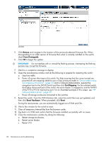
The following standards are maintained in the sample configurations, Dual domain, Single domain
 |
View all HP P2000 manuals
Add to My Manuals
Save this manual to your list of manuals |
Page 53 highlights
The following standards are maintained in the sample configurations: Device SAS BL switches: P2000 G3 SAS MSA Array controller modules: Cabling: Single domain Dual domain Depending on the type of server blade used, one or two switches are installed in the c-Class enclosure, providing a single path between the server blades and the switches. nl When using full-height or half-height server blades, one switch is required. Depending on the type of server blade used, two or four switches are installed in the c-Class enclosure, providing dual paths between the server blades and the switches. nl When using full-height or half-height server blades, two switches are required, installed in adjacent interconnect bays, for example, in interconnect bays 5 and 6. One controller is installed in P2000 G3 SAS MSA Array controller enclosures, providing a single path between the switch and the P2000 G3 SAS MSA Array. Two controllers are installed in P2000 G3 SAS MSA Array controller enclosures, providing an alternate path between the switches and the P2000 G3 SAS MSA Array. A single cable is connected between the Two cables are connected between the switch and the storage enclosure. If ports switch and the storage enclosure: one from on the switch and the storage enclosure the primary controller or I/O module and are available, connect an additional cable one from the secondary controller or I/O between the devices, for improved module. If ports on the switch and the performance. storage enclosure are available, connect an additional cable between the devices, for improved performance. Introduction 53
-
 1
1 -
2
-
3
-
4
-
5
-
6
-
7
-
8
-
9
-
10
-
11
-
12
-
13
-
14
-
15
-
16
-
17
-
18
-
19
-
20
-
21
-
22
-
23
-
24
-
25
-
26
-
27
-
28
-
29
-
30
-
31
-
32
-
33
-
34
-
35
-
36
-
37
-
38
-
39
-
40
-
41
-
42
-
43
-
44
-
45
-
46
-
47
-
 48
48 -
 49
49 -
 50
50 -
 51
51 -
 52
52 -
 53
53 -
 54
54 -
 55
55 -
 56
56 -
 57
57 -
 58
58 -
59
-
60
-
61
-
62
-
63
-
64
-
65
-
66
-
67
-
68
-
69
-
70
-
71
-
72
-
73
-
74
 |
 |