HP P6000 HP Controller Enclosure LED Display Replacement Instructions (593093- - Page 4
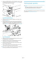
Verifying proper operation
 |
View all HP P6000 manuals
Add to My Manuals
Save this manual to your list of manuals |
Page 4 highlights
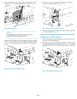
3. With the pins fully extended out of the LED display membrane, align the display with the holes on the enclosure (1, Figure 8), and then press the display against the enclosure. Verifying proper operation NOTE: Wait approximately three minutes for the system to check the status of components after the enclosure is powered on. After replacing the LED display, check the indicators for proper operation as described in Verifying component failure. Figure 8 Attaching the LED display . 4. Push the two pins on the display membrane into the holes in the enclosure (2, Figure 8). 5. Attach the baffle near the display cable by placing the flange of the baffle over the thin chassis wall, and sliding the baffle down and forward so the small tab on the baffle goes into the slot in the chassis (1, Figure 9). Tighten the baffle thumbscrew (2, Figure 9). Figure 9 Attaching baffle . 6. Reattach the top access panel by sliding the panel onto the enclosure and tightening the cover thumbscrew. 7. Reinstall the enclosure into the rack (observing the two-man lift requirements), and reattach the enclosure front bezel. 8. Reattach all cables (Fibre Channel and/or SAS, Ethernet, power) to the enclosure components. 9. Power up attached disk enclosures by pressing the power button on the rear power UID bezel of each disk enclosure. 10. Power up the controller enclosure by pressing the power button on the rear power UID bezel of the controller enclosure. Page 4
-
 1
1 -
 2
2 -
 3
3 -
 4
4
 |
 |
