HP Pavilion 13-b100 Pavilion 13 Notebook PC - Page 59
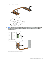
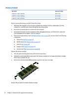
Lift the left side of the heat sink, until the heat sink has clearance for release.
 |
View all HP Pavilion 13-b100 manuals
Add to My Manuals
Save this manual to your list of manuals |
Page 59 highlights
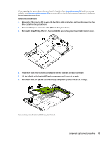
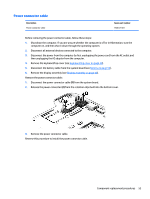
When replacing the system board, be sure that the heat sink (see Heat sink on page 50) and the memory modules (see Memory module on page 52) are removed from the defective system board and installed on the replacement system board. Remove the system board: 1. Release the ZIF connector (1) to which the hard drive cable is attached, and then disconnect the hard drive cable from the system board. 2. Disconnect the power connector cable (2) from the system board. 3. Remove the three Phillips PM2.4×5.7 screws (3) that secure the system board to the bottom cover. 4. Flex the left side of the bottom cover (1) until the heat sink has clearance for release. 5. Lift the left side of the heat sink (2) and system board until it rests at an angle. 6. Remove the heat sink (3) and system board by sliding them up and to the left at an angle. Reverse this procedure to install the system board. Component replacement procedures 49
-
 1
1 -
2
-
3
-
4
-
5
-
6
-
7
-
8
-
9
-
10
-
11
-
12
-
13
-
14
-
15
-
16
-
17
-
18
-
19
-
20
-
21
-
22
-
23
-
24
-
25
-
26
-
27
-
28
-
29
-
30
-
31
-
32
-
33
-
34
-
35
-
36
-
37
-
38
-
39
-
40
-
41
-
42
-
43
-
44
-
45
-
46
-
47
-
48
-
49
-
50
-
51
-
52
-
53
-
 54
54 -
 55
55 -
 56
56 -
 57
57 -
 58
58 -
 59
59 -
 60
60 -
 61
61 -
 62
62 -
 63
63 -
 64
64 -
65
-
66
-
67
-
68
-
69
-
70
-
71
-
72
-
73
-
74
-
75
-
76
-
77
-
78
-
79
-
80
-
81
-
82
-
83
-
84
-
85
-
86
-
87
 |
 |
