HP Pavilion 15-bk100 Maintenance and Service Guide - Page 63
use only on computer models with model numbers 15-bk000 through 15-bk099.
 |
View all HP Pavilion 15-bk100 manuals
Add to My Manuals
Save this manual to your list of manuals |
Page 63 highlights
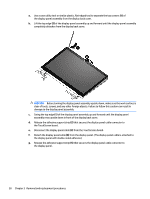
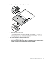
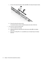
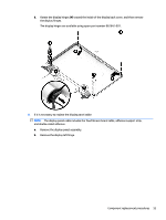
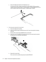
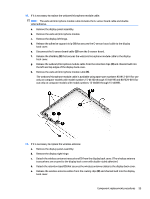
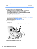
10. If it is necessary to replace the webcam/microphone module cable: NOTE: The webcam/microphone module cable includes the G-sensor board cable and doublesided adhesive. a. Remove the display panel assembly. b. Remove the webcam/microphone module. c. Remove the display left hinge. d. Release the adhesive support strip (1) that secures the G-sensor board cable to the display back cover. e. Disconnect the G-sensor board cable (2) from the G-sensor board. f. Release the shielding (3) that secures the webcam/microphone module cable to the display back cover. g. Release the webcam/microphone module cable from the retention clips (4) and channel built into the left and top edges of the display back cover. h. Remove the webcam/microphone module cable (5). The webcam/microphone module cable is available using spare part numbers 903912-001 (for use only on computer models with model numbers 15-bk100 through 15-bk199) and 807529-001 (for use only on computer models with model numbers 15-bk000 through 15-bk099). 11. If it is necessary to replace the wireless antenna: a. Remove the display panel assembly. b. Remove the display right hinge. c. Detach the wireless antenna transceivers (1) from the display back cover. (The wireless antenna transceivers are secured to the display back cover with double-sided adhesive.) d. Detach the retention tape (2) that secures the wireless antenna cables to the display back cover. e. Release the wireless antenna cables from the routing clips (3) and channel built into the display back cover. Component replacement procedures 55
-
 1
1 -
2
-
3
-
4
-
5
-
6
-
7
-
8
-
9
-
10
-
11
-
12
-
13
-
14
-
15
-
16
-
17
-
18
-
19
-
20
-
21
-
22
-
23
-
24
-
25
-
26
-
27
-
28
-
29
-
30
-
31
-
32
-
33
-
34
-
35
-
36
-
37
-
38
-
39
-
40
-
41
-
42
-
43
-
44
-
45
-
46
-
47
-
48
-
49
-
50
-
51
-
52
-
53
-
54
-
55
-
56
-
57
-
 58
58 -
 59
59 -
 60
60 -
 61
61 -
 62
62 -
 63
63 -
 64
64 -
 65
65 -
 66
66 -
 67
67 -
 68
68 -
69
-
70
-
71
-
72
-
73
-
74
-
75
-
76
-
77
-
78
-
79
-
80
-
81
-
82
-
83
-
84
 |
 |
