HP Pavilion 15-p200 Pavilion 17 Notebook PC Pavilion 15 Notebook PC Maintenanc - Page 18
Left side
 |
View all HP Pavilion 15-p200 manuals
Add to My Manuals
Save this manual to your list of manuals |
Page 18 highlights
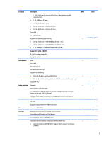
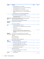
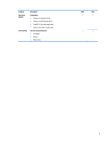
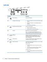
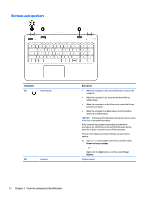
Left side Component (1) Power connector (2) AC adapter and battery light (3) RJ-45 (network) jack/status lights (4) Vents (2) (5) HDMI port (6) USB 3.0 ports (2) (7) Memory card reader Description Connects an AC adapter. ● White: The AC adapter is connected and the battery is fully charged. ● Amber: The AC adapter is connected and the battery is charging. ● Off: The battery is not charging. Connects a network cable. ● White: The network is connected. ● Amber: Activity is occurring on the network. Enable airflow to cool internal components. NOTE: The computer fan starts up automatically to cool internal components and prevent overheating. It is normal for the internal fan to cycle on and off during routine operation. Connects an optional video or audio device, such as a highdefinition television, any compatible digital or audio component, or a high-speed High-Definition Multimedia Interface (HDMI) device. Connects an optional USB device, such as a keyboard, mouse, external drive, printer, scanner or USB hub. Reads optional memory cards that enable you to store, manage, share, or access information. To insert a card: 1. Hold the card label-side up, with connectors facing the computer. 2. Insert the card into the memory card reader, and then press in on the card until it is firmly seated. To remove a card: ▲ Press in on the card, and then remove it from the memory card reader. 8 Chapter 2 External component identification
-
 1
1 -
2
-
3
-
4
-
5
-
6
-
7
-
8
-
9
-
10
-
11
-
12
-
 13
13 -
 14
14 -
 15
15 -
 16
16 -
 17
17 -
 18
18 -
 19
19 -
 20
20 -
 21
21 -
 22
22 -
 23
23 -
24
-
25
-
26
-
27
-
28
-
29
-
30
-
31
-
32
-
33
-
34
-
35
-
36
-
37
-
38
-
39
-
40
-
41
-
42
-
43
-
44
-
45
-
46
-
47
-
48
-
49
-
50
-
51
-
52
-
53
-
54
-
55
-
56
-
57
-
58
-
59
-
60
-
61
-
62
-
63
-
64
-
65
-
66
-
67
-
68
-
69
-
70
-
71
-
72
-
73
-
74
-
75
-
76
-
77
-
78
-
79
-
80
-
81
-
82
-
83
-
84
-
85
-
86
-
87
-
88
-
89
-
90
-
91
-
92
-
93
-
94
-
95
-
96
-
97
-
98
-
99
-
100
-
101
-
102
-
103
-
104
-
105
-
106
-
107
-
108
-
109
-
110
-
111
-
112
-
113
-
114
-
115
-
116
-
117
-
118
-
119
-
120
-
121
-
122
-
123
-
124
-
125
-
126
-
127
-
128
 |
 |
