HP Pavilion HDX9110TX HP Pavilion HDX Entertainment Notebook PC - Maintenance - Page 49
and the top and bottom edges
 |
View all HP Pavilion HDX9110TX manuals
Add to My Manuals
Save this manual to your list of manuals |
Page 49 highlights
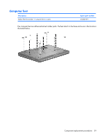
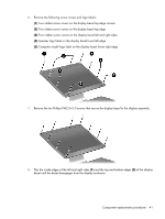
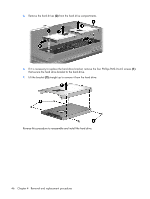
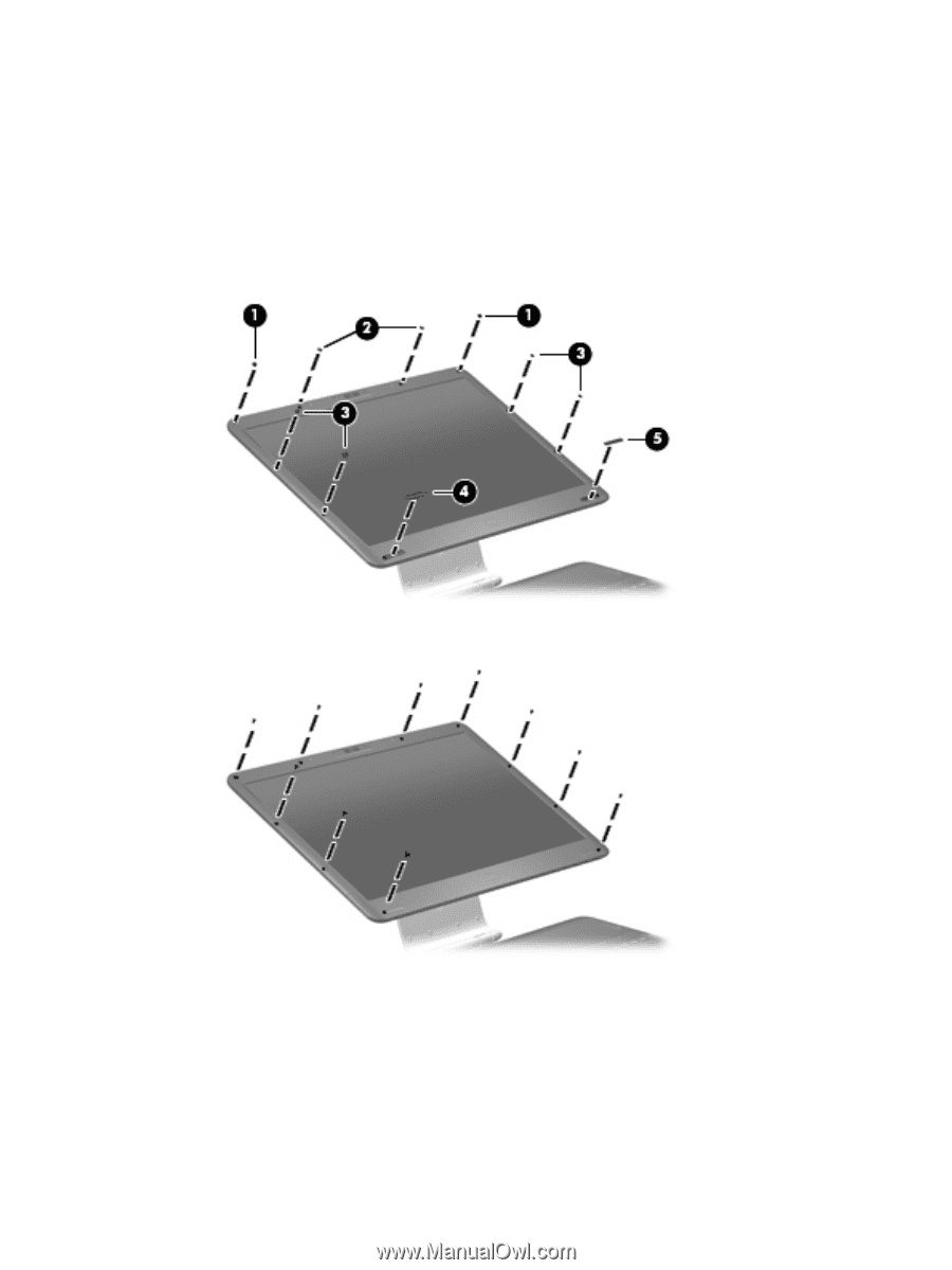
6. Remove the following screw covers and logo labels: (1) Two rubber screw covers on the display bezel top edge corners (2) Two rubber screw covers on the display bezel top edge (3) Four rubber screw covers on the display bezel left and right sides (4) Speaker logo label on the display bezel lower left edge (5) Computer model logo label on the display bezel lower right edge 7. Remove the ten Phillips PM2.5×5.0 screws that secure the display bezel to the display assembly. 8. Flex the inside edges of the left and right sides (1) and the top and bottom edges (2) of the display bezel until the bezel disengages from the display enclosure. Component replacement procedures 41
-
 1
1 -
2
-
3
-
4
-
5
-
6
-
7
-
8
-
9
-
10
-
11
-
12
-
13
-
14
-
15
-
16
-
17
-
18
-
19
-
20
-
21
-
22
-
23
-
24
-
25
-
26
-
27
-
28
-
29
-
30
-
31
-
32
-
33
-
34
-
35
-
36
-
37
-
38
-
39
-
40
-
41
-
42
-
43
-
 44
44 -
 45
45 -
 46
46 -
 47
47 -
 48
48 -
 49
49 -
 50
50 -
 51
51 -
 52
52 -
 53
53 -
 54
54 -
55
-
56
-
57
-
58
-
59
-
60
-
61
-
62
-
63
-
64
-
65
-
66
-
67
-
68
-
69
-
70
-
71
-
72
-
73
-
74
-
75
-
76
-
77
-
78
-
79
-
80
-
81
-
82
-
83
-
84
-
85
-
86
-
87
-
88
-
89
-
90
-
91
-
92
-
93
-
94
-
95
-
96
-
97
-
98
-
99
-
100
-
101
-
102
-
103
-
104
-
105
-
106
-
107
-
108
-
109
-
110
-
111
-
112
-
113
-
114
-
115
-
116
-
117
-
118
-
119
-
120
-
121
-
122
-
123
-
124
-
125
-
126
-
127
-
128
-
129
-
130
-
131
-
132
-
133
-
134
-
135
-
136
-
137
-
138
-
139
-
140
-
141
-
142
-
143
-
144
-
145
-
146
-
147
-
148
-
149
-
150
-
151
-
152
-
153
-
154
-
155
-
156
-
157
-
158
-
159
-
160
-
161
-
162
-
163
 |
 |
6
.
Remove the following screw covers and logo labels:
(1)
Two rubber screw covers on the display bezel top edge corners
(2)
Two rubber screw covers on the display bezel top edge
(3)
Four rubber screw covers on the display bezel left and right sides
(4)
Speaker logo label on the display bezel lower left edge
(5)
Computer model logo label on the display bezel lower right edge
7
.
Remove the ten Phillips PM2.5×5.0 screws that secure the display bezel to the display assembly.
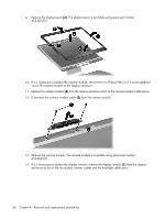
8
.
Flex the inside edges of the left and right sides
(1)
and the top and bottom edges
(2)
of the display
bezel until the bezel disengages from the display enclosure.
Component replacement procedures
41