HP Pavilion TouchSmart 14-b150us HP Pavilion TouchSmart 14 Ultrabook HP Pavili - Page 89
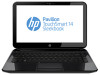
If it is necessary to replace the webcam/microphone module, Remove the display assembly subcomponents
 |
View all HP Pavilion TouchSmart 14-b150us manuals
Add to My Manuals
Save this manual to your list of manuals |
Page 89 highlights
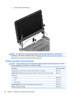
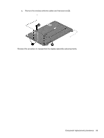
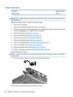
IMPORTANT: Make special note of each screw and screw lock size and location during removal and replacement. Before removing the display assembly, follow these steps: 1. Shut down the computer. 2. Disconnect all external devices connected to the computer. 3. Disconnect the power from the computer by first unplugging the power cord from the AC outlet and then unplugging the AC adapter from the computer. 4. Remove the battery (see Battery on page 42). 5. Remove the display panel (see Display panel on page 44). 6. Remove the keyboard (see Keyboard on page 46). 7. Remove the top cover (see Top cover on page 50). 8. Remove the hard drive (see Hard drive on page 54). 9. Remove the USB board (see USB board/audio jack on page 57). 10. Remove the WLAN (see WLAN module on page 58). 11. Remove the system board (see System board on page 61). 12. Remove the display assembly (see Display assembly on page 78 Remove the display assembly subcomponents: 1. If it is necessary to replace the webcam/microphone module: a. Detach and release the webcam/microphone module as far as the webcam/microphone module cable allows. (The webcam/microphone module is attached to the back cover with double-sided tape.) b. Disconnect the webcam/microphone cable (1) from the webcam/microphone module. c. Remove the webcam/microphone module (2). Component replacement procedures 81
-
 1
1 -
2
-
3
-
4
-
5
-
6
-
7
-
8
-
9
-
10
-
11
-
12
-
13
-
14
-
15
-
16
-
17
-
18
-
19
-
20
-
21
-
22
-
23
-
24
-
25
-
26
-
27
-
28
-
29
-
30
-
31
-
32
-
33
-
34
-
35
-
36
-
37
-
38
-
39
-
40
-
41
-
42
-
43
-
44
-
45
-
46
-
47
-
48
-
49
-
50
-
51
-
52
-
53
-
54
-
55
-
56
-
57
-
58
-
59
-
60
-
61
-
62
-
63
-
64
-
65
-
66
-
67
-
68
-
69
-
70
-
71
-
72
-
73
-
74
-
75
-
76
-
77
-
78
-
79
-
80
-
81
-
82
-
83
-
 84
84 -
 85
85 -
 86
86 -
 87
87 -
 88
88 -
 89
89 -
 90
90 -
 91
91 -
 92
92 -
 93
93 -
 94
94 -
95
-
96
-
97
-
98
-
99
-
100
-
101
-
102
-
103
-
104
-
105
-
106
-
107
-
108
-
109
-
110
-
111
-
112
-
113
-
114
-
115
-
116
-
117
-
118
-
119
 |
 |
