HP Pavilion TouchSmart 14-n018us HP Pavilion 14 Notebook PC HP Pavilion TouchS - Page 101
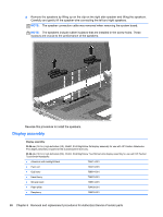
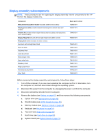
Display assembly subcomponents, Component, Spare part number, Webcamera/microphone module
 |
View all HP Pavilion TouchSmart 14-n018us manuals
Add to My Manuals
Save this manual to your list of manuals |
Page 101 highlights
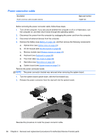
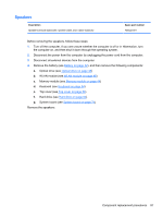
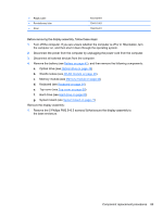
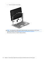
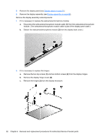
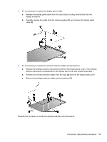
Display assembly subcomponents NOTE: These procedures are for replacing the display assembly internal components for the HP Pavilion flat display models only. Component Webcamera/microphone module (includes adhesive and screws) Display panel cable (includes webcamera/microphone module cable and screws) Antenna Kit (includes left and right wireless antenna cables and transceivers and 2 rubber screws) Display Hinge Kit (includes left and right hinges and rubber screws) Display back cover (includes 2 rubber screws): Aluminum with midnight black finish Flyer red finish Goji berry finish Hazel berry finish Mineral black finish Pearl white finish Raspberry finish Regal purple finish Revolutionary blue finish Silver finish Spare part number 725665-001 734407-001 734400-001 734408-001 734405-001 734401-001 736810-001 736811-001 736809-001 726193-001 736812-001 734403-001 734402-001 734404-001 Before removing the display assembly subcomponents, follow these steps: 1. Turn off the computer. If you are unsure whether the computer is off or in Hibernation, turn the computer on, and then shut it down through the operating system. 2. Disconnect the power from the computer by unplugging the power cord from the computer. 3. Disconnect all external devices from the computer. 4. Remove the battery (see Battery on page 42), and then remove the following components: a. Optical drive (see Optical drive on page 48) b. WLAN module (see WLAN module on page 46) c. Memory module (see Memory module on page 44) d. Keyboard (see Keyboard on page 54) e. Top cover (see Top cover on page 59) f. Hard drive (see Hard drive on page 63) g. System board (see System board on page 71) Component replacement procedures 91
-
 1
1 -
2
-
3
-
4
-
5
-
6
-
7
-
8
-
9
-
10
-
11
-
12
-
13
-
14
-
15
-
16
-
17
-
18
-
19
-
20
-
21
-
22
-
23
-
24
-
25
-
26
-
27
-
28
-
29
-
30
-
31
-
32
-
33
-
34
-
35
-
36
-
37
-
38
-
39
-
40
-
41
-
42
-
43
-
44
-
45
-
46
-
47
-
48
-
49
-
50
-
51
-
52
-
53
-
54
-
55
-
56
-
57
-
58
-
59
-
60
-
61
-
62
-
63
-
64
-
65
-
66
-
67
-
68
-
69
-
70
-
71
-
72
-
73
-
74
-
75
-
76
-
77
-
78
-
79
-
80
-
81
-
82
-
83
-
84
-
85
-
86
-
87
-
88
-
89
-
90
-
91
-
92
-
93
-
94
-
95
-
 96
96 -
 97
97 -
 98
98 -
 99
99 -
 100
100 -
 101
101 -
 102
102 -
 103
103 -
 104
104 -
 105
105 -
 106
106 -
107
-
108
-
109
-
110
-
111
-
112
-
113
-
114
-
115
-
116
-
117
-
118
-
119
-
120
-
121
-
122
-
123
-
124
-
125
-
126
-
127
-
128
-
129
-
130
 |
 |