HP Pavilion dm4-1100 HP Pavilion dm4 Entertainment PC - Maintenance and Servic - Page 76
Display assembly
 |
View all HP Pavilion dm4-1100 manuals
Add to My Manuals
Save this manual to your list of manuals |
Page 76 highlights
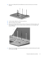
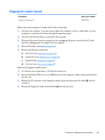
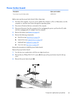
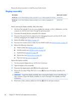
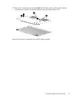
Reverse the above procedure to install the power button board. Display assembly Description Spare part number 35.56 cm (14.0-in) WXGA Brightview display assembly for use in models equipped with WWAN 613667-001 35.56 cm (14.0-in) WXGA Brightview display assembly for use in models not equipped with WWAN 608207-001 Before removing the display assembly, follow these steps: 1. Shut down the computer. If you are unsure whether the computer is off or in Hibernation, turn the computer on, and then shut it down through the operating system. 2. Disconnect all external devices connected to the computer. 3. Disconnect the power from the computer by first unplugging the power cord from the AC outlet and then unplugging the AC adapter from the computer. 4. Remove the battery (see Battery on page 42). 5. Disconnect the wireless antenna cables from the WLAN module (see WLAN module on page 47). 6. Remove the following components: a. WLAN module (see WLAN module on page 47) b. WWAN module (see WWAN module on page 52) c. Keyboard (see Keyboard on page 58) d. Optical drive (see Optical drive on page 56) e. Top cover (see Top cover on page 60) Remove the display assembly: 1. Turn the computer display-side up, with the front toward you. 2. Open the display as far as possible. 3. Disconnect the display panel cable (1) from the system board. 4. Remove the four black Phillips PM2.5×6.5 screws (2) that secure the display assembly to the computer. CAUTION: Support the display assembly when removing the display screws in the following steps. Failure to support the display assembly can result in damage to the assembly and other components. 5. Remove the wireless antenna cables from the hole (3) built into the base enclosure. 66 Chapter 4 Removal and replacement procedures
-
 1
1 -
2
-
3
-
4
-
5
-
6
-
7
-
8
-
9
-
10
-
11
-
12
-
13
-
14
-
15
-
16
-
17
-
18
-
19
-
20
-
21
-
22
-
23
-
24
-
25
-
26
-
27
-
28
-
29
-
30
-
31
-
32
-
33
-
34
-
35
-
36
-
37
-
38
-
39
-
40
-
41
-
42
-
43
-
44
-
45
-
46
-
47
-
48
-
49
-
50
-
51
-
52
-
53
-
54
-
55
-
56
-
57
-
58
-
59
-
60
-
61
-
62
-
63
-
64
-
65
-
66
-
67
-
68
-
69
-
70
-
 71
71 -
 72
72 -
 73
73 -
 74
74 -
 75
75 -
 76
76 -
 77
77 -
 78
78 -
 79
79 -
 80
80 -
 81
81 -
82
-
83
-
84
-
85
-
86
-
87
-
88
-
89
-
90
-
91
-
92
-
93
-
94
-
95
-
96
-
97
-
98
-
99
-
100
-
101
-
102
-
103
-
104
-
105
-
106
-
107
-
108
-
109
-
110
-
111
-
112
-
113
-
114
-
115
-
116
-
117
-
118
-
119
-
120
-
121
-
122
-
123
-
124
-
125
-
126
-
127
-
128
-
129
 |
 |