HP Pavilion dm4-1200 HP Pavilion dm4 Entertainment PC - Maintenance and Servic - Page 71
access to the cables.
 |
View all HP Pavilion dm4-1200 manuals
Add to My Manuals
Save this manual to your list of manuals |
Page 71 highlights
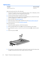
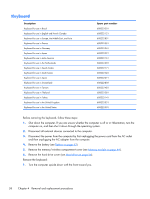
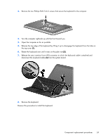
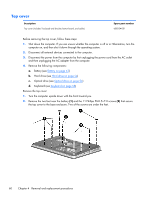
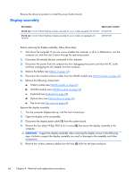
3. Remove the six Phillips PM2.0x2.0 broadhead screws that secure the top cover to the base enclosure. 4. Turn the computer right-side up with the front toward you. 5. Open the computer as far as possible. 6. Remove the four Phillips PM2.0×4.0 screws that secure the top cover to the base enclosure, and then disengage the top cover from the base enclosure and lift the top cover up enough to gain access to the cables. 7. Release the ZIF connector to which the power button board is connected and disconnect the cable from the system board (1). Component replacement procedures 61
-
 1
1 -
2
-
3
-
4
-
5
-
6
-
7
-
8
-
9
-
10
-
11
-
12
-
13
-
14
-
15
-
16
-
17
-
18
-
19
-
20
-
21
-
22
-
23
-
24
-
25
-
26
-
27
-
28
-
29
-
30
-
31
-
32
-
33
-
34
-
35
-
36
-
37
-
38
-
39
-
40
-
41
-
42
-
43
-
44
-
45
-
46
-
47
-
48
-
49
-
50
-
51
-
52
-
53
-
54
-
55
-
56
-
57
-
58
-
59
-
60
-
61
-
62
-
63
-
64
-
65
-
 66
66 -
 67
67 -
 68
68 -
 69
69 -
 70
70 -
 71
71 -
 72
72 -
 73
73 -
 74
74 -
 75
75 -
 76
76 -
77
-
78
-
79
-
80
-
81
-
82
-
83
-
84
-
85
-
86
-
87
-
88
-
89
-
90
-
91
-
92
-
93
-
94
-
95
-
96
-
97
-
98
-
99
-
100
-
101
-
102
-
103
-
104
-
105
-
106
-
107
-
108
-
109
-
110
-
111
-
112
-
113
-
114
-
115
-
116
-
117
-
118
-
119
-
120
-
121
-
122
-
123
-
124
-
125
-
126
-
127
-
128
-
129
 |
 |

3.
Remove the six Phillips PM2.0x2.0 broadhead screws that secure the top cover to the base
enclosure.
4.
Turn the computer right-side up with the front toward you.
5.
Open the computer as far as possible.
6.
Remove the four Phillips PM2.0×4.0 screws that secure the top cover to the base enclosure, and
then disengage the top cover from the base enclosure and lift the top cover up enough to gain
access to the cables.
7.
Release the ZIF connector to which the power button board is connected and disconnect the cable
from the system board
(1)
.
Component replacement procedures
61