HP Pavilion dm4-1200 HP Pavilion dm4 Entertainment PC - Maintenance and Servic - Page 77
that secure the brackets to base enclosure, and the remove the brackets
 |
View all HP Pavilion dm4-1200 manuals
Add to My Manuals
Save this manual to your list of manuals |
Page 77 highlights
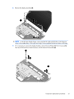
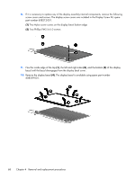
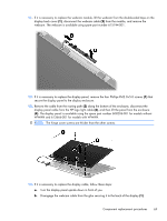
6. Remove the display assembly (4). NOTE: In the left main display hinge, screws populate the right and left holes in the hinge (no screw in the middle hole). In the right main hinge, screws populate the left two holes in the hinge. 7. If it is necessary to remove the display brackets, remove the two Phillips PM2.0×3.0 screws (1) that secure the brackets to base enclosure, and the remove the brackets (2). Component replacement procedures 67
-
 1
1 -
2
-
3
-
4
-
5
-
6
-
7
-
8
-
9
-
10
-
11
-
12
-
13
-
14
-
15
-
16
-
17
-
18
-
19
-
20
-
21
-
22
-
23
-
24
-
25
-
26
-
27
-
28
-
29
-
30
-
31
-
32
-
33
-
34
-
35
-
36
-
37
-
38
-
39
-
40
-
41
-
42
-
43
-
44
-
45
-
46
-
47
-
48
-
49
-
50
-
51
-
52
-
53
-
54
-
55
-
56
-
57
-
58
-
59
-
60
-
61
-
62
-
63
-
64
-
65
-
66
-
67
-
68
-
69
-
70
-
71
-
 72
72 -
 73
73 -
 74
74 -
 75
75 -
 76
76 -
 77
77 -
 78
78 -
 79
79 -
 80
80 -
 81
81 -
 82
82 -
83
-
84
-
85
-
86
-
87
-
88
-
89
-
90
-
91
-
92
-
93
-
94
-
95
-
96
-
97
-
98
-
99
-
100
-
101
-
102
-
103
-
104
-
105
-
106
-
107
-
108
-
109
-
110
-
111
-
112
-
113
-
114
-
115
-
116
-
117
-
118
-
119
-
120
-
121
-
122
-
123
-
124
-
125
-
126
-
127
-
128
-
129
 |
 |

6.
Remove the display assembly
(4)
.
NOTE:
In the left main display hinge, screws populate the right and left holes in the hinge (no
screw in the middle hole). In the right main hinge, screws populate the left two holes in the hinge.
7.
If it is necessary to remove the display brackets, remove the two Phillips PM2.0×3.0 screws
(1)
that secure the brackets to base enclosure, and the remove the brackets
(2)
.
Component replacement procedures
67