HP Pavilion dv7-3000 HP Pavilion dv7 Entertainment PC - Maintenance and Servic - Page 100
and on the Northbridge chip, on the processor and contact
 |
View all HP Pavilion dv7-3000 manuals
Add to My Manuals
Save this manual to your list of manuals |
Page 100 highlights
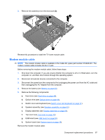
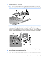
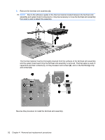
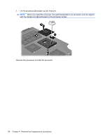
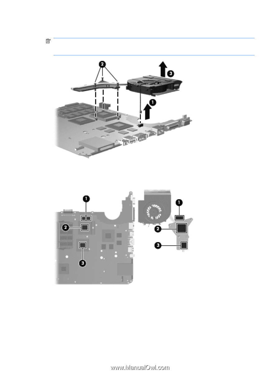
8. Remove the fan/heat sink assembly (3). NOTE: Due to the adhesive quality of the thermal material located between the fan/heat sink assembly and system board components, it may be necessary to move the fan/heat sink assembly from side to side to detach the assembly. The thermal material must be thoroughly cleaned from the surfaces of the fan/heat sink assembly and the system board each time the fan/heat sink assembly is removed. Thermal paste is used on capacitors and their contacts (1), on the processor and contact (2), and on the Northbridge chip and contact (3). Reverse this procedure to install the fan/heat sink assembly. 92 Chapter 4 Removal and replacement procedures
-
 1
1 -
2
-
3
-
4
-
5
-
6
-
7
-
8
-
9
-
10
-
11
-
12
-
13
-
14
-
15
-
16
-
17
-
18
-
19
-
20
-
21
-
22
-
23
-
24
-
25
-
26
-
27
-
28
-
29
-
30
-
31
-
32
-
33
-
34
-
35
-
36
-
37
-
38
-
39
-
40
-
41
-
42
-
43
-
44
-
45
-
46
-
47
-
48
-
49
-
50
-
51
-
52
-
53
-
54
-
55
-
56
-
57
-
58
-
59
-
60
-
61
-
62
-
63
-
64
-
65
-
66
-
67
-
68
-
69
-
70
-
71
-
72
-
73
-
74
-
75
-
76
-
77
-
78
-
79
-
80
-
81
-
82
-
83
-
84
-
85
-
86
-
87
-
88
-
89
-
90
-
91
-
92
-
93
-
94
-
 95
95 -
 96
96 -
 97
97 -
 98
98 -
 99
99 -
 100
100 -
 101
101 -
 102
102 -
 103
103 -
 104
104 -
 105
105 -
106
-
107
-
108
-
109
-
110
-
111
-
112
-
113
-
114
-
115
-
116
-
117
-
118
-
119
-
120
-
121
-
122
-
123
-
124
-
125
-
126
-
127
-
128
-
129
-
130
-
131
-
132
-
133
-
134
-
135
-
136
-
137
-
138
-
139
-
140
-
141
-
142
-
143
-
144
-
145
-
146
-
147
-
148
-
149
-
150
-
151
-
152
-
153
-
154
-
155
-
156
-
157
-
158
-
159
-
160
-
161
-
162
-
163
-
164
 |
 |
8.
Remove the fan/heat sink assembly
(3)
.
NOTE:
Due to the adhesive quality of the thermal material located between the fan/heat sink
assembly and system board components, it may be necessary to move the fan/heat sink assembly
from side to side to detach the assembly.
The thermal material must be thoroughly cleaned from the surfaces of the fan/heat sink assembly
and the system board each time the fan/heat sink assembly is removed. Thermal paste is used on
capacitors and their contacts
(1)
, on the processor and contact
(2)
, and on the Northbridge chip
and contact
(3)
.
Reverse this procedure to install the fan/heat sink assembly.
92
Chapter 4
Removal and replacement procedures