HP Pavilion g6-1a00 HP Pavilion G6 Notebook PC - Maintenance and Service Guide - Page 74
System board, USB board see
 |
View all HP Pavilion g6-1a00 manuals
Add to My Manuals
Save this manual to your list of manuals |
Page 74 highlights
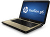
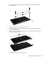
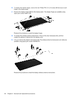
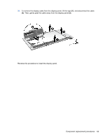
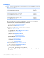
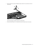
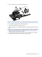
System board NOTE: The system board spare part kit includes UMA or discrete graphics subsystem memory and replacement thermal material. Description For use in Intel HM55 UMA computer models For use in Intel HM65 UMA computer models For use in Intel HM55 discrete, 512 MB, computer models For use in Intel HM55 discrete, 1 GB, computer models For use in Intel HM65 discrete, 512 MB, computer models For use in Intel HM65 discrete, 1 GB, computer models For use in AMD UMA computer models Spare part number 639521-001 639522-001 639523-001 639524-001 639525-001 639526-001 640893-001 When replacing the system board, be sure that the following components are removed from the defective system board and installed on the replacement system board: ● Memory modules (see Memory module on page 45) ● WLAN module (see WLAN module on page 43) Before removing the system board, remove the following components: 1. Battery (see Battery on page 37) 2. Service access cover (see Service access cover on page 38) 3. Hard drive (see Hard drive on page 39) 4. Optical drive (see Optical drive on page 41) 5. WLAN module (see WLAN module on page 43) 6. Memory module (see Memory module on page 45) 7. Keyboard (see Keyboard on page 47) 8. Top cover (see Top cover on page 49) 9. USB board (see USB board on page 56) 10. Display assembly (see Display assembly on page 59) 11. Power connector (see Power connector on page 58) Remove the optical drive connector board: 1. Turn the computer right-side up, with the front toward you. 2. Remove the three Phillips 4.0 x 2.5 screws (1) that secure the optical drive connector board to the computer. 66 Chapter 4 Removal and replacement procedures
-
 1
1 -
2
-
3
-
4
-
5
-
6
-
7
-
8
-
9
-
10
-
11
-
12
-
13
-
14
-
15
-
16
-
17
-
18
-
19
-
20
-
21
-
22
-
23
-
24
-
25
-
26
-
27
-
28
-
29
-
30
-
31
-
32
-
33
-
34
-
35
-
36
-
37
-
38
-
39
-
40
-
41
-
42
-
43
-
44
-
45
-
46
-
47
-
48
-
49
-
50
-
51
-
52
-
53
-
54
-
55
-
56
-
57
-
58
-
59
-
60
-
61
-
62
-
63
-
64
-
65
-
66
-
67
-
68
-
 69
69 -
 70
70 -
 71
71 -
 72
72 -
 73
73 -
 74
74 -
 75
75 -
 76
76 -
 77
77 -
 78
78 -
 79
79 -
80
-
81
-
82
-
83
-
84
-
85
-
86
-
87
-
88
-
89
-
90
-
91
-
92
-
93
-
94
-
95
-
96
-
97
-
98
-
99
-
100
-
101
-
102
-
103
-
104
-
105
-
106
-
107
-
108
-
109
-
110
 |
 |