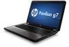
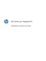
HP Pavilion g7-1000 HP Pavilion g7 Notebook PC - Maintenance and Service Guide
HP Pavilion g7-1000 Manual
 |
View all HP Pavilion g7-1000 manuals
Add to My Manuals
Save this manual to your list of manuals |
HP Pavilion g7-1000 manual content summary:
- HP Pavilion g7-1000 | HP Pavilion g7 Notebook PC - Maintenance and Service Guide - Page 1
HP Pavilion g7 Notebook PC Maintenance and Service Guide - HP Pavilion g7-1000 | HP Pavilion g7 Notebook PC - Maintenance and Service Guide - Page 2
to change without notice. The only warranties for HP products and services are set forth in the express warranty statements accompanying such products and services. Nothing herein should be construed as constituting an additional warranty. HP shall not be liable for technical or editorial errors - HP Pavilion g7-1000 | HP Pavilion g7 Notebook PC - Maintenance and Service Guide - Page 3
Safety warning notice WARNING! To reduce the possibility of heat-related injuries or of overheating the device, do not place the device directly on your lap or obstruct the device air vents. Use the device only on a hard, flat surface. Do not allow another hard surface, such as an adjoining optional - HP Pavilion g7-1000 | HP Pavilion g7 Notebook PC - Maintenance and Service Guide - Page 4
iv Safety warning notice - HP Pavilion g7-1000 | HP Pavilion g7 Notebook PC - Maintenance and Service Guide - Page 5
Button ...9 Keys ...10 Lights ...11 TouchPad ...12 Display ...13 Front ...14 Left side ...14 Right side ...15 Bottom ...16 3 Illustrated parts catalog 17 Service tag ...17 Computer major components 18 Cable Kit ...25 Display assembly subcomponents 26 Mass storage devices ...28 Miscellaneous parts - HP Pavilion g7-1000 | HP Pavilion g7 Notebook PC - Maintenance and Service Guide - Page 6
Packaging and transporting guidelines 40 Component replacement procedures 42 Service tag ...42 Computer feet ...43 Battery ...44 Optical board ...70 Power connector cable 71 System board ...73 Optical drive cable 77 Fan and heat sink ...79 Processor ...86 Display assembly ...89 5 Setup Utility ( - HP Pavilion g7-1000 | HP Pavilion g7 Notebook PC - Maintenance and Service Guide - Page 7
6 Specifications ...102 Computer specifications ...102 17.3-inch display specifications 103 Hard drive specifications ...104 7 Backup and recovery ...105 Restore ...105 Creating restore media ...106 Performing a system restore 107 Restoring using the dedicated recovery partition (select models - HP Pavilion g7-1000 | HP Pavilion g7 Notebook PC - Maintenance and Service Guide - Page 8
viii - HP Pavilion g7-1000 | HP Pavilion g7 Notebook PC - Maintenance and Service Guide - Page 9
1 Product description Category Product Name Processors Description HP Pavilion g7 Notebook PC AMD Athlon II P360 2.30-GHz processor (1.0-MB L2 cache, 1066-MHz, 3.2GT/sec, dual core, 25 W) AMD Athlon II P340 2.20-GHz processor (1.0-MB - HP Pavilion g7-1000 | HP Pavilion g7 Notebook PC - Maintenance and Service Guide - Page 10
Northbridge: AMD RS880MD √ Southbridge: AMD SB820M Intel® HM65 and HM55 Express chipset Internal graphics: ATi Mobility Radeon™ √ HD 4250 graphics supporting DX10.1 Internal graphics: ● Intel HD Graphics 3000 ● Intel HD Graphics 100 ● Intel HD Graphics Computer models equipped with an Intel - HP Pavilion g7-1000 | HP Pavilion g7 Notebook PC - Maintenance and Service Guide - Page 11
DDR3 @ 900 MHz × 4 PCs), 64-bit S3 package, muxless switchable Supports DX11 √ Support HD decode, DX11, and wireless local area network (WLAN) antenna cables Supports 16:9 ultra wide aspect ratio 2 customer-accessible/upgradable memory √ module slots Supports dual-channel memory √ Supports - HP Pavilion g7-1000 | HP Pavilion g7 Notebook PC - Maintenance and Service Guide - Page 12
speakers √ Supports Microsoft Premium requirements √ HP VGA webcam (fixed, no tilt with activity √ LED, 640×480 by 24 frames per second Ethernet Integrated 10/100 network interface card √ (NIC) Wireless Integrated wireless local area network √ (WLAN) options by way of wireless module - HP Pavilion g7-1000 | HP Pavilion g7 Notebook PC - Maintenance and Service Guide - Page 13
/b/g/n 2×2 WiFi and Bluetooth 3.0+HS Combo Adapter Support for the following WLAN formats: ● Intel Centrino Wireless-N 1000 WLAN module ● Intel Centrino Advanced-N 6230 ● Intel Centrino Wireless-N 1000 HP Multi-Format Digital Media Reader √ supports the following digital card formats: ● Secure - HP Pavilion g7-1000 | HP Pavilion g7 Notebook PC - Maintenance and Service Guide - Page 14
@ 60Hz and 1920 ×1200 @ 60Hz in DVI mode ● RJ-45 (Ethernet, includes link and activity lights) ● USB 2.0 (3 ports) ● VGA (Dsub 15 pin) supporting 2048×1056 external resolution @ 75 Hz, 1920 ×1200 external resolution @ 60Hz, hot plug and unplug and autodetection for correct output to wideaspect vs - HP Pavilion g7-1000 | HP Pavilion g7 Notebook PC - Maintenance and Service Guide - Page 15
Category Serviceability Description Computer models equipped with an AMD processor Preinstalled: ● Windows 7 Home Basic (64- and 32-bit) ● Windows 7 Home Premium (64- and 32bit) ● Windows 7 Professional (64- - HP Pavilion g7-1000 | HP Pavilion g7 Notebook PC - Maintenance and Service Guide - Page 16
2 External component identification 8 Chapter 2 External component identification - HP Pavilion g7-1000 | HP Pavilion g7 Notebook PC - Maintenance and Service Guide - Page 17
to turn off the computer. To learn more about your power settings, select Start > Control Panel > System and Security > Power Options, or refer to the HP Notebook Reference Guide. Top 9 - HP Pavilion g7-1000 | HP Pavilion g7 Notebook PC - Maintenance and Service Guide - Page 18
Keys Item (1) (2) (3) (4) (5) (6) Component esc key fn key Windows logo key Action keys Windows applications key Integrated numeric keypad Description Displays system information when pressed in combination with the fn key. Displays system information when pressed in combination with the esc key. - HP Pavilion g7-1000 | HP Pavilion g7 Notebook PC - Maintenance and Service Guide - Page 19
Item (1) (2) (3) (4) Component TouchPad light Caps lock light Power light Wireless light Description ● Amber: The TouchPad is off. ● Off: The TouchPad computer is off or in Hibernation. ● White: An integrated wireless device, such as a WLAN device and/or a Bluetooth device, is on. ● Amber: All - HP Pavilion g7-1000 | HP Pavilion g7 Notebook PC - Maintenance and Service Guide - Page 20
TouchPad Item (1) (2) (3) (4) (5) Component TouchPad light TouchPad on/off button TouchPad zone Left TouchPad button Right TouchPad button Description ● Amber: The TouchPad is off. ● On: The TouchPad is on. Turns the TouchPad on and off. Quickly double-tap the TouchPad on/off button to turn the - HP Pavilion g7-1000 | HP Pavilion g7 Notebook PC - Maintenance and Service Guide - Page 21
Component Description (1) WLAN antennas (2)* Send and receive wireless signals to communicate with WLANs. (2) Webcam light On optimal transmission, keep the areas immediately around the antennas free from obstructions. To see wireless regulatory notices, refer to the section of the Regulatory, - HP Pavilion g7-1000 | HP Pavilion g7 Notebook PC - Maintenance and Service Guide - Page 22
. Enable airflow to cool internal components. NOTE: The computer fan starts up automatically to cool internal components and prevent overheating. It is normal for the internal fan to cycle on and off during routine operation. Connects a network - HP Pavilion g7-1000 | HP Pavilion g7 Notebook PC - Maintenance and Service Guide - Page 23
Item (8) Component Digital Media Slot (9) (10) Drive light Power light Right side Description Supports the following digital card formats: ● Secure Digital (SD) Memory Card ● Secure Digital High Capacity (SDHC) Memory Card ● Secure Digital Extended Capacity (SDXC) Memory Card ● MultiMediaCard - HP Pavilion g7-1000 | HP Pavilion g7 Notebook PC - Maintenance and Service Guide - Page 24
by the governmental agency that regulates wireless devices in your country or region. If you replace the module and then receive a warning message, remove the module to restore computer functionality, and then contact technical support through Help and Support. 16 Chapter 2 External component - HP Pavilion g7-1000 | HP Pavilion g7 Notebook PC - Maintenance and Service Guide - Page 25
information about the product's hardware components. The part number helps a service technician to determine what components and parts are needed. This is the alphanumeric identifier needed to locate documents, drivers, and support for the computer. This number describes the duration of the warranty - HP Pavilion g7-1000 | HP Pavilion g7 Notebook PC - Maintenance and Service Guide - Page 26
Computer major components 18 Chapter 3 Illustrated parts catalog - HP Pavilion g7-1000 | HP Pavilion g7 Notebook PC - Maintenance and Service Guide - Page 27
Spare part number 17.3-in, high definition (HD), light-emitting diode (LED), BrightView display assembly (includes webcam, two microphones, and wireless antenna transceivers and cables) In butter gold finish 640223-001 In charcoal gray finish 640226-001 In luminous rose finish 640225-001 In - HP Pavilion g7-1000 | HP Pavilion g7 Notebook PC - Maintenance and Service Guide - Page 28
Item (3) Component For use in the United States Keyboard in silver finish For use in Belgium For use in Canada For use in the Czech Republic For use in Denmark, Finland, and Norway For use in France For use in Germany For use in Greece For use in Hungary For use in Israel For use in Italy For use - HP Pavilion g7-1000 | HP Pavilion g7 Notebook PC - Maintenance and Service Guide - Page 29
Item (4) (5) (6) (7a) (7b) (7c) (8) (9) (10) (11) (12) (13) Component Spare part number Power button board (includes cable) 640212-001 TouchPad LED board (includes cable) 640213-001 TouchPad button board (includes cable) 640214-001 Cable Kit, includes: 640206-001 TouchPad cable Optical - HP Pavilion g7-1000 | HP Pavilion g7 Notebook PC - Maintenance and Service Guide - Page 30
Item (14) Component Spare part number For use only with computer models equipped with an HM55 chipset and a graphics subsystem with UMA video memory 636370-001 Thermal Material Kit (includes replacement thermal paste and pads) 634433-001 Processor (includes replacement thermal material) AMD - HP Pavilion g7-1000 | HP Pavilion g7 Notebook PC - Maintenance and Service Guide - Page 31
(3.0-MB L3 cache, dual core, 35 W) 625831-001 Intel Pentium P6300 2.26-GHz processor (3.0-MB L3 cache, dual core, 35 W) 635500-001 Fan (includes replacement thermal material) 639460-001 Heat sink (includes replacement thermal material) For use only with computer models equipped with an AMD - HP Pavilion g7-1000 | HP Pavilion g7 Notebook PC - Maintenance and Service Guide - Page 32
with an Intel processor: Atheros 9285G 802.11b/g/n 1×1 WiFi Adapter 518436-001 Intel Centrino Advanced-N 6230 631956-001 Intel Centrino Wireless-N 1000 593530-001 Service cover (includes 2 captive screws, secured by C-clips) - available in the Plastics Kit, spare part number 640216-001) 24 - HP Pavilion g7-1000 | HP Pavilion g7 Notebook PC - Maintenance and Service Guide - Page 33
Cable Kit Item (1) (2) (3) Component Cable Kit, includes: TouchPad cable Hard drive connector cable Optical drive cable Spare part number 640206-001 Cable Kit 25 - HP Pavilion g7-1000 | HP Pavilion g7 Notebook PC - Maintenance and Service Guide - Page 34
display hinges and brackets) Display Cable Kit (includes display panel cable and webcam/microphone module cable) Antenna Kit (includes left and right wireless antenna cables and transceivers) Spare part number 640204-001 643698-001 637197-001 641395-001 640207-001 640205-001 640192-001 26 Chapter - HP Pavilion g7-1000 | HP Pavilion g7 Notebook PC - Maintenance and Service Guide - Page 35
Item (8) Component Display enclosure: In butter gold finish In charcoal gray finish In luminous rose finish In ocean drive finish In Pacific blue finish In pearl pink finish In pewter finish In Sonoma red finish In sweet purple finish Display Screw Kit (not illustrated) Spare part number 640197- - HP Pavilion g7-1000 | HP Pavilion g7 Notebook PC - Maintenance and Service Guide - Page 36
Mass storage devices Item (1) (2a) (2b) (2c) (3) Component Spare part number Hard drive (2.5-in, 7.0-mm, SATA, does not include hard drive connector cable, isolators, or Mylar shield): For use with all computer models: 750-GB, 5400-rpm 644351-001 640-GB, 5400-rpm 637312-001 500-GB, 7200- - HP Pavilion g7-1000 | HP Pavilion g7 Notebook PC - Maintenance and Service Guide - Page 37
Multi Double-Layer Drive DVD±RW and CD-RW Super Multi Double-Layer Combo Drive with LightScribe Miscellaneous parts Component HP Smart AC adapter 90-W PFC RC V HP Smart AC adapter 65-W RC V HP Smart AC adapter Power cord (3-pin, black, 1.83-m): For use in Denmark For use in Europe For use in - HP Pavilion g7-1000 | HP Pavilion g7 Notebook PC - Maintenance and Service Guide - Page 38
ready) for use only with computer models equipped with an AMD processor Intel Centrino Wireless-N 1000 WLAN module for use only on computer models equipped with an Intel processor 6-cell .11b/g/n 1×1 WiFi Adapter 65-W RC V HP Smart AC adapter for use only with computer models equipped with an AMD processor - HP Pavilion g7-1000 | HP Pavilion g7 Notebook PC - Maintenance and Service Guide - Page 39
Spare part number 616333-001 616343-001 616345-001 621565-001 621569-001 625823-001 625831-001 630703-001 630705-001 631252-001 631253-001 631255-001 631956-001 634433-001 634687-001 634688-001 634689-001 634691-001 634692-001 634693-001 635494-001 635495-001 Description AMD V140 2.30-GHz processor - HP Pavilion g7-1000 | HP Pavilion g7 Notebook PC - Maintenance and Service Guide - Page 40
Spare part number 635496-001 635500-001 636370-001 636371-001 636372-001 636373-001 636374-001 636375-001 636634-001 636635-001 637189-001 637190-001 637193-001 637197-001 637312-001 638037-001 638039-001 638854-001 638855-001 Description AMD Phenom II N970 2.20-GHz processor (2.0-MB L2 cache, 1333 - HP Pavilion g7-1000 | HP Pavilion g7 Notebook PC - Maintenance and Service Guide - Page 41
replacement thermal material) Rubber Feet Kit (includes 4 rubber feet) Fan (includes replacement thermal material) Heat sink for use only with computer (DDR3, 10600, 1333-MHz) Antenna Kit (includes left and right wireless antenna cables and transceivers) Top cover in Sonoma red finish (includes - HP Pavilion g7-1000 | HP Pavilion g7 Notebook PC - Maintenance and Service Guide - Page 42
(includes cable) LED board (includes cable) Plastics Kit (includes the service cover) Screw Kit Display Screw Kit 17.3-in, HD, LED, BrightView wireless antenna transceivers and cables) 17.3-in, HD, LED, BrightView display assembly in sweet purple finish (includes webcam, two microphones, and wireless - HP Pavilion g7-1000 | HP Pavilion g7 Notebook PC - Maintenance and Service Guide - Page 43
antenna transceivers and cables) 17.3-in, HD, LED, BrightView display assembly in pearl pink finish (includes webcam, two microphones, and wireless antenna transceivers and cables) Realtek RTL8191SE 802.11b/g/n 1×1 WiFi Adapter for use only with computer models equipped with an AMD processor Heat - HP Pavilion g7-1000 | HP Pavilion g7 Notebook PC - Maintenance and Service Guide - Page 44
Spare part number 647630-001 647630-031 647630-041 647630-051 647630-061 647630-071 647630-121 647630-131 647630-141 647630-171 647630-211 647630-221 647630-251 647630-A41 647630-B31 647630-BA1 647630-BB1 647630-BG1 647630-DH1 647630-DJ1 Description Keyboard in silver finish for use in the United - HP Pavilion g7-1000 | HP Pavilion g7 Notebook PC - Maintenance and Service Guide - Page 45
at the points designated in the maintenance instructions. Cables and connectors CAUTION: When servicing the computer, be sure that cables are connector whenever possible. In all cases, avoid bending, twisting, or tearing cables. Be sure that cables are routed in such a way that they cannot be caught - HP Pavilion g7-1000 | HP Pavilion g7 Notebook PC - Maintenance and Service Guide - Page 46
(ESD). Circuitry design and structure determine the degree of sensitivity. Networks built into many integrated circuits provide some protection, but in many cases, ESD contains enough power to alter device parameters or melt silicon junctions. A discharge of static electricity from a finger or other - HP Pavilion g7-1000 | HP Pavilion g7 Notebook PC - Maintenance and Service Guide - Page 47
CAUTION: To prevent damage to the computer when you are removing or installing internal components, observe these precautions: Keep components in their electrostatic-safe containers until you are ready to install them. Before touching an electronic component, discharge static electricity by using - HP Pavilion g7-1000 | HP Pavilion g7 Notebook PC - Maintenance and Service Guide - Page 48
and use properly grounded tools and equipment. ● Use conductive field service tools, such as cutters, screwdrivers, and vacuums. ● When -sensitive components, parts, and assemblies by the case or PCM laminate. Handle these items only at static-free workstations. ● Avoid contact with pins, leads, - HP Pavilion g7-1000 | HP Pavilion g7 Notebook PC - Maintenance and Service Guide - Page 49
with ground cords of one megohm resistance ● Static-dissipative tables or floor mats with hard ties to the ground ● Field service kits ● Static awareness labels ● Material-handling packages ● Nonconductive plastic bags, tubes, or boxes ● Metal tote boxes ● Electrostatic voltage levels and - HP Pavilion g7-1000 | HP Pavilion g7 Notebook PC - Maintenance and Service Guide - Page 50
information about the product's hardware components. The part number helps a service technician to determine what components and parts are needed. This is the alphanumeric identifier needed to locate documents, drivers, and support for the computer. This number describes the duration of the warranty - HP Pavilion g7-1000 | HP Pavilion g7 Notebook PC - Maintenance and Service Guide - Page 51
Computer feet The computer feet are adhesive-backed rubber pads. The feet are included in the Rubber Feet Kit, spare part number 639455-001. There are 4 rubber feet that attach to the base enclosure in the locations illustrated below. Component replacement procedures 43 - HP Pavilion g7-1000 | HP Pavilion g7 Notebook PC - Maintenance and Service Guide - Page 52
Battery Description 6-cell, 55-Whr, 2.55-Ah Li-ion battery 6-cell, 47-Whr, 2.20-Ah Li-ion battery Spare part number 593554-001 593553-001 Before disassembling the computer, follow these steps: 1. Shut down the computer. If you are unsure whether the computer is off or in Hibernation, turn the - HP Pavilion g7-1000 | HP Pavilion g7 Notebook PC - Maintenance and Service Guide - Page 53
the optical drive: 1. Loosen the two captive screws (1) that secure the service cover to the computer. 2. Lift the rear edge of the service cover (2) up and forward until it rests at an angle. 3. Remove the service cover. The service cover is available in the Plastics Kit, spare part number 640216 - HP Pavilion g7-1000 | HP Pavilion g7 Notebook PC - Maintenance and Service Guide - Page 54
5. Remove the optical drive (2) by sliding it out of the optical drive bay. 6. If it is necessary to replace the optical drive bracket, position the optical drive with the rear panel toward you. 7. Remove the two Phillips PM2.0×4.0 screws (1) that secure the bracket to the optical drive. 8. Remove - HP Pavilion g7-1000 | HP Pavilion g7 Notebook PC - Maintenance and Service Guide - Page 55
from the AC outlet and then unplugging the AC adapter from the computer. 4. Remove the battery (see Battery on page 44). 5. Remove the service cover (see Optical drive on page 45). Remove the hard drive: 1. Disconnect the hard drive connector cable (1) from the system board. Component replacement - HP Pavilion g7-1000 | HP Pavilion g7 Notebook PC - Maintenance and Service Guide - Page 56
2. Lift the front edge of the hard drive (2) until it rests at an angle. 3. Remove the hard drive. 4. If it is necessary to replace the hard drive connector cable (1), the hard drive isolators (2), or the Mylar shield (3) from the hard drive, remove and replace the components. Reverse this procedure - HP Pavilion g7-1000 | HP Pavilion g7 Notebook PC - Maintenance and Service Guide - Page 57
cord from the AC outlet and then unplugging the AC adapter from the computer. 4. Remove the battery (see Battery on page 44). 5. Remove the service cover (see Optical drive on page 45). Remove the RTC battery: 1. Disconnect the RTC battery cable (1) from the system board. 2. Slide the RTC battery - HP Pavilion g7-1000 | HP Pavilion g7 Notebook PC - Maintenance and Service Guide - Page 58
power cord from the AC outlet and then unplugging the AC adapter from the computer. 4. Remove the battery (see Battery on page 44). 5. Remove the service cover (see Optical drive on page 45). Remove the memory module: 1. Spread the retaining tabs (1) on each side of the memory module slot to release - HP Pavilion g7-1000 | HP Pavilion g7 Notebook PC - Maintenance and Service Guide - Page 59
Wireless-N 1000 Spare wireless devices in your country or region. If you replace the module and then receive a warning message, remove the module to restore device functionality, and then contact technical support service cover (see Optical drive on page 45). Component replacement procedures - HP Pavilion g7-1000 | HP Pavilion g7 Notebook PC - Maintenance and Service Guide - Page 60
Remove the WLAN module: 1. Disconnect the WLAN antenna cables (1) from the terminals on the WLAN module. NOTE: The 1/black WLAN antenna cable is connected to the WLAN module 1/Main terminal. The 2/gray WLAN antenna cable is connected to the WLAN module 2/Aux terminal. 2. Remove the Phillips PM2 - HP Pavilion g7-1000 | HP Pavilion g7 Notebook PC - Maintenance and Service Guide - Page 61
Keyboard NOTE: The keyboard spare part kit includes a keyboard cable. Description Keyboard in black finish: For use in Belgium For use in Canada For use in the Czech Republic For use in Denmark, Finland, and Norway For use in France For use in Germany For use in Greece For use in Hungary For use in - HP Pavilion g7-1000 | HP Pavilion g7 Notebook PC - Maintenance and Service Guide - Page 62
4. Remove the battery (see Battery on page 44). 5. Remove the service cover (see Optical drive on page 45). Remove the keyboard: 1. Remove the Phillips PM2.5×7.0 screw that secures the keyboard to the computer. 2. Rest the computer - HP Pavilion g7-1000 | HP Pavilion g7 Notebook PC - Maintenance and Service Guide - Page 63
4. Insert a screw driver or similar thin tool into the keyboard screw hole, and then press on the back of the keyboard until the keyboard disengages from the computer. 5. - HP Pavilion g7-1000 | HP Pavilion g7 Notebook PC - Maintenance and Service Guide - Page 64
7. Release the zero insertion force (ZIF) connector (1) to which the keyboard cable is attached, and then disconnect the keyboard cable (2) from the system board. 8. Remove the keyboard. Reverse this procedure to install the keyboard. 56 Chapter 4 Removal and replacement procedures - HP Pavilion g7-1000 | HP Pavilion g7 Notebook PC - Maintenance and Service Guide - Page 65
Top cover NOTE: The top cover spare part kit includes the TouchPad and TouchPad cable. Description In butter gold finish In charcoal gray finish In luminous rose finish In ocean drive finish In Pacific blue finish In pearl pink finish In pewter finish In Sonoma red finish In sweet purple finish - HP Pavilion g7-1000 | HP Pavilion g7 Notebook PC - Maintenance and Service Guide - Page 66
3. Remove the 12 Phillips PM2.5×7.0 screws that secure the top cover to the computer. 4. Remove the two Phillips PM2.5×7.0 screws (1) in the hard drive bay and the three Phillips PM2.5×6.0 screws (2) in the battery bay that secure the top cover to the computer. 5. Turn the computer right-side up, - HP Pavilion g7-1000 | HP Pavilion g7 Notebook PC - Maintenance and Service Guide - Page 67
8. Remove the Phillips PM2.5×6.0 screw (1) that secures the top cover to the computer. 9. Lift the rear edge of the top cover (2) until the left and right sides disengage from the base enclosure. 10. Remove the top cover (3). Reverse this procedure to install the top cover. Component replacement - HP Pavilion g7-1000 | HP Pavilion g7 Notebook PC - Maintenance and Service Guide - Page 68
Power button board Description Power button board (includes cable) Spare part number 640212-001 Before removing the power button board, follow these steps: 1. Shut down the computer. If you are unsure whether the computer is off or in Hibernation, turn the computer on, and then shut it down - HP Pavilion g7-1000 | HP Pavilion g7 Notebook PC - Maintenance and Service Guide - Page 69
5. Remove the power button board and cable by sliding the board up and to the right at an angle (4). Reverse this procedure to install the power button board and cable. Component replacement procedures 61 - HP Pavilion g7-1000 | HP Pavilion g7 Notebook PC - Maintenance and Service Guide - Page 70
TouchPad button board Description TouchPad button board (includes cable) Spare part number 640214-001 Before removing the TouchPad button board, follow these steps: 1. Shut down the computer. If you are unsure whether the computer is off or in Hibernation, turn the computer on, and then shut it - HP Pavilion g7-1000 | HP Pavilion g7 Notebook PC - Maintenance and Service Guide - Page 71
5. Lift the rear edge of the TouchPad button board (6) until it is released from the clips built into the top cover. 6. Remove the TouchPad button board and cable. Reverse this procedure to install the TouchPad button board and cable. TouchPad LED board Description TouchPad LED board (includes - HP Pavilion g7-1000 | HP Pavilion g7 Notebook PC - Maintenance and Service Guide - Page 72
Remove the TouchPad LED board and cable: 1. Turn the top cover upside down, with the front toward you. 2. Release the ZIF connector (1) to which the TouchPad LED board cable is connected, and then disconnect the TouchPad LED board cable (2) from the TouchPad button board. 3. Release the TouchPad LED - HP Pavilion g7-1000 | HP Pavilion g7 Notebook PC - Maintenance and Service Guide - Page 73
Bluetooth module NOTE: This section applies only to computer models equipped with an Intel processor. Description Bluetooth module NOTE: The Bluetooth module spare part kit does not include a Bluetooth module cable. The Bluetooth module cable is available using spare part number 602538-001. Spare - HP Pavilion g7-1000 | HP Pavilion g7 Notebook PC - Maintenance and Service Guide - Page 74
2. Release the clips (2) built into the base enclosure that secure the Bluetooth module, and then remove the module (3) from the clips. 3. If it is necessary to replace the Bluetooth module cable, disconnect the cable from the Bluetooth module and replace it. 66 Chapter 4 Removal and replacement - HP Pavilion g7-1000 | HP Pavilion g7 Notebook PC - Maintenance and Service Guide - Page 75
Reverse this procedure to install the Bluetooth module and cable. Speakers Description Speaker Kit (includes left and right speakers and cable) Spare part number 641396-001 Before removing the speakers, follow these steps: 1. Shut down the computer. If you are unsure whether the computer is off or - HP Pavilion g7-1000 | HP Pavilion g7 Notebook PC - Maintenance and Service Guide - Page 76
Reverse this procedure to install the speakers. LED board Description LED board Spare part number 640215-001 Before removing the LED board, follow these steps: 1. Shut down the computer. If you are unsure whether the computer is off or in Hibernation, turn the computer on, and then shut it down - HP Pavilion g7-1000 | HP Pavilion g7 Notebook PC - Maintenance and Service Guide - Page 77
4. Remove the LED board and cable by sliding the board (5) up and to the right at an angle. Reverse this procedure to install the LED board and cable. Component replacement procedures 69 - HP Pavilion g7-1000 | HP Pavilion g7 Notebook PC - Maintenance and Service Guide - Page 78
USB board Description USB board (includes cable) Spare part number 640211-001 Before removing the USB board, follow these steps: 1. Shut down the computer. If you are unsure whether the computer is off or in Hibernation, turn the computer on, and then shut it down through the operating system. 2. - HP Pavilion g7-1000 | HP Pavilion g7 Notebook PC - Maintenance and Service Guide - Page 79
3. Remove the USB board (4) and cable. Reverse this procedure to install the USB board. Power connector cable Description Power connector cable Spare part number 641394-001 Before removing the power connector cable, follow these steps: 1. Shut down the computer. If you are unsure whether the - HP Pavilion g7-1000 | HP Pavilion g7 Notebook PC - Maintenance and Service Guide - Page 80
Remove the power connector cable: 1. Disconnect the power connector cable (1) from the system board. 2. Release the power connector cable (2) from the clips (3) built into the base enclosure. 3. Remove the power connector (4) from the clip (5) built into the base enclosure. Reverse this procedure to - HP Pavilion g7-1000 | HP Pavilion g7 Notebook PC - Maintenance and Service Guide - Page 81
System board NOTE: The system board spare part kit includes replacement thermal material. Replacement thermal material is also available in the Thermal Material Kit, spare part number 634433-001. Description For use only with computer models equipped with an AMD processor: For use only with - HP Pavilion g7-1000 | HP Pavilion g7 Notebook PC - Maintenance and Service Guide - Page 82
are removed from the defective system board and installed on the replacement system board: ● Memory module (see Memory module on page 50) ● Fan and heat sink (see Fan and heat sink on page 79) ● Processor (see Processor on page 86) Remove the system board: 1. Disconnect the following cables from the - HP Pavilion g7-1000 | HP Pavilion g7 Notebook PC - Maintenance and Service Guide - Page 83
4. Release the ZIF connector to which the USB board cable is attached, and then disconnect the USB cable (2) from the system board. 5. Lift the right side of the system board (1) until it rests at an angle. Component replacement procedures 75 - HP Pavilion g7-1000 | HP Pavilion g7 Notebook PC - Maintenance and Service Guide - Page 84
with computer models equipped with an AMD processor have the Southbridge chip located on the bottom of the board. A thermal pad is used on the Southbridge chip (1) and the base enclosure heat sink (2) that services it. The thermal material must be thoroughly cleaned from the surfaces of the system - HP Pavilion g7-1000 | HP Pavilion g7 Notebook PC - Maintenance and Service Guide - Page 85
Reverse this procedure to install the system board. Optical drive cable NOTE: The optical drive cable is included in the Cable Kit, spare part number 640206-001. The optical drive cable includes the optical drive connector. Before removing the optical drive cable, follow these steps: 1. Shut down - HP Pavilion g7-1000 | HP Pavilion g7 Notebook PC - Maintenance and Service Guide - Page 86
2. Release the clips (3) built into the base enclosure that secure the optical drive connector, and then release the connector (4) from the clips. 3. Remove the optical drive connector and cable. Reverse this procedure to install the optical drive connector and cable. 78 Chapter 4 Removal and - HP Pavilion g7-1000 | HP Pavilion g7 Notebook PC - Maintenance and Service Guide - Page 87
fast charging, and software requirements. Exhaust air is displaced through the ventilation grill located on the left side of the computer. Before removing the fan and heat sink, follow these steps: 1. Shut down the computer. If you are unsure whether the computer is off or in Hibernation, turn the - HP Pavilion g7-1000 | HP Pavilion g7 Notebook PC - Maintenance and Service Guide - Page 88
have three captive screws. Computer models equipped with an Intel processor have four captive screws.) 4. Remove the three Phillips PM2.5×6.0 screws (3) that secure the fan and heat sink to the system board. NOTE: Due to the adhesive quality of the thermal material located between the heat sink and - HP Pavilion g7-1000 | HP Pavilion g7 Notebook PC - Maintenance and Service Guide - Page 89
graphics subsystem with discrete memory. NOTE: The following illustration shows the fan and heat sink being removed from a computer model equipped with an graphics subsystem with UMA memory. See steps 2 through 5 for fan and heat sink removal information for computer models equipped with a graphics - HP Pavilion g7-1000 | HP Pavilion g7 Notebook PC - Maintenance and Service Guide - Page 90
board components, it may be necessary to move the heat sink from side to side to detach it. 8. Remove the fan and heat sink (3). NOTE: The following illustration shows the fan and heat sink removal process on a computer model equipped with an AMD processor and a graphics subsystem with UMA memory - HP Pavilion g7-1000 | HP Pavilion g7 Notebook PC - Maintenance and Service Guide - Page 91
removed. Replacement thermal material is included with the base enclosure, fan, heat sink, processor, and system board spare part kits. heat sink section (2) that services it ● A thermal pad is used on the Northbridge chip (3) and the heat sink section (4) that services it ● A thermal pad - HP Pavilion g7-1000 | HP Pavilion g7 Notebook PC - Maintenance and Service Guide - Page 92
them ● A thermal pad is used on the graphics subsystem chip (3) and the heat sink section (4) that services it NOTE: The following illustration shows the replacement thermal material locations on a computer model equipped with an Intel processor and a graphics subsystem with UMA memory. - HP Pavilion g7-1000 | HP Pavilion g7 Notebook PC - Maintenance and Service Guide - Page 93
Remove the two Phillips PM2.0×3.0 screws (1) that secure the fan to the heat sink. b. Release the two clips (2) that secure the fan to the heat sink. c. Remove the fan (3) from the heat sink. Reverse this procedure to reassemble and install the fan and heat sink. Component replacement procedures 85 - HP Pavilion g7-1000 | HP Pavilion g7 Notebook PC - Maintenance and Service Guide - Page 94
Processor NOTE: The processor spare part kit includes replacement thermal material. Replacement thermal material is also available in the Thermal Material Kit, spare part number 634433-001. Description Spare part number AMD Athlon II P360 2.30-GHz processor (1.0-MB L2 cache, 1066-MHz, 3.2GT/sec, - HP Pavilion g7-1000 | HP Pavilion g7 Notebook PC - Maintenance and Service Guide - Page 95
cover (see Top cover on page 57) ● System board (see System board on page 73) ● Fan and heat sink (see Fan and heat sink on page 79) Remove the processor: 1. Use a flat-bladed screw driver (1) to turn the processor locking screw one-half turn counterclockwise (2), until you hear a click. Component - HP Pavilion g7-1000 | HP Pavilion g7 Notebook PC - Maintenance and Service Guide - Page 96
2. Lift the processor (3) straight up, and remove it. NOTE: The gold triangle (4) on the processor must be aligned with the triangle icon embossed on the processor socket when you install the processor. NOTE: The following illustration shows the processor removal process on a computer model equipped - HP Pavilion g7-1000 | HP Pavilion g7 Notebook PC - Maintenance and Service Guide - Page 97
this procedure to install the processor. Display assembly NOTE: The display assembly spare part kit includes webcam, two microphones, and wireless antenna transceivers and cables). Description Spare part number 17.3-in, HD, LED, BrightView display assembly (includes webcam, two microphones, and - HP Pavilion g7-1000 | HP Pavilion g7 Notebook PC - Maintenance and Service Guide - Page 98
the display panel cable (1) from the system board. 2. Release the wireless antenna cables (2) from the clips and the opening in the base enclosure. CAUTION: Support the display assembly when removing the following screws. Failure to support the display assembly can result in damage to the display - HP Pavilion g7-1000 | HP Pavilion g7 Notebook PC - Maintenance and Service Guide - Page 99
Display Screw Kit, spare part number 640218-001. b. Flex the inside edges of the top edge (1), the left and right sides (2), and the bottom edge (3) of the display bezel until the bezel disengages from the display enclosure. c. Remove the display bezel (4). The display bezel is available using spare - HP Pavilion g7-1000 | HP Pavilion g7 Notebook PC - Maintenance and Service Guide - Page 100
b. Disconnect the webcam/microphone module (2) from the webcam/microphone module. c. Remove the webcam/microphone module. The webcam/microphone module is available using spare part number 637197-001. 7. If it is necessary to replace the hinge covers: a. Remove the two Phillips PM2.5×6.0 (1) screws - HP Pavilion g7-1000 | HP Pavilion g7 Notebook PC - Maintenance and Service Guide - Page 101
8. If it is necessary to replace the display panel: a. Remove the four Phillips PM2.5×6.0 screws that secure the display panel to the display enclosure. b. Lift the top edge of the display panel, and then swing it up and forward until it rests upside down in front of the display enclosure. Component - HP Pavilion g7-1000 | HP Pavilion g7 Notebook PC - Maintenance and Service Guide - Page 102
c. Release the adhesive strip (1) that secures the display panel cable to the display panel, and then disconnect the display panel cable (2) from the display panel. d. Remove the display panel. The display panel is available using spare part number 641395-001. 9. If it is necessary to replace the - HP Pavilion g7-1000 | HP Pavilion g7 Notebook PC - Maintenance and Service Guide - Page 103
Kit, spare part number 640205-001. 11. If it is necessary to replace the wireless antenna cables and transceivers: a. Release the wireless antenna transceivers (1) from the display enclosure. (The wireless antenna transceivers are attached to the display enclosure with double-sided tape.) b. Release - HP Pavilion g7-1000 | HP Pavilion g7 Notebook PC - Maintenance and Service Guide - Page 104
c. Remove the wireless antenna cables and transceivers (3). The wireless antenna cables and transceivers are available in the Antenna Kit, spare part number 640192-001. Reverse this procedure to reassemble and install the display assembly. 96 Chapter 4 Removal and replacement procedures - HP Pavilion g7-1000 | HP Pavilion g7 Notebook PC - Maintenance and Service Guide - Page 105
to a USB port can be used with Setup Utility only if USB legacy support is enabled. To start Setup Utility, follow these steps: 1. Turn on or while the "Press the ESC key for Startup Menu" message is displayed at the bottom of the screen. 2. Press f10 to enter Setup Utility. Changing the language of - HP Pavilion g7-1000 | HP Pavilion g7 Notebook PC - Maintenance and Service Guide - Page 106
esc while the "Press the ESC key for Startup Menu" message is displayed at the bottom of the screen. ● To select a menu or a menu item, use the tab key icon in the lower-left corner of the screen, and then follow the on-screen instructions. - or - Use the tab key and the arrow keys to select File > - HP Pavilion g7-1000 | HP Pavilion g7 Notebook PC - Maintenance and Service Guide - Page 107
"Press the ESC key for Startup Menu" message is displayed at the bottom of the screen. 2. Press f10 to enter Setup Utility. 3. Use a pointing device or the arrow keys to select File > Restore Defaults. 4. Follow the on-screen instructions. 5. To save your changes and exit, click the Save icon in the - HP Pavilion g7-1000 | HP Pavilion g7 Notebook PC - Maintenance and Service Guide - Page 108
, or disconnect any device, cable, or cord. 1. Windows 7-Select Start > Help and Support > Maintain. Windows XP-Select Start > Help and Support, and then select the software and drivers update. 2. Follow the on-screen instructions to identify your computer and access the BIOS update you want to - HP Pavilion g7-1000 | HP Pavilion g7 Notebook PC - Maintenance and Service Guide - Page 109
the installation by following the on-screen instructions. NOTE: After a message on the screen test repeats the start-up test and checks for intermittent problems that the start-up test does not detect. ● If the battery fails the test, contact HP support to report the issue and purchase a replacement - HP Pavilion g7-1000 | HP Pavilion g7 Notebook PC - Maintenance and Service Guide - Page 110
6 Specifications Computer specifications Metric U.S. Dimensions Depth 26.8 cm 10.6 in Width 41.2 cm 16.2 in Height 3.1 to 3.7 cm 1.2 to 1.5 in Weight 2.97 kg 6.55 lb Input power Operating voltage 18.5 V dc @ 3.5 A - 65 W or 19.0 V dc @ 4.74 A - 90 W Operating current 3.5 or 4.74 - HP Pavilion g7-1000 | HP Pavilion g7 Notebook PC - Maintenance and Service Guide - Page 111
17.3-inch display specifications Dimensions Height Width Diagonal Number of colors Contrast ratio Brightness Pixel resolution Pitch Format Configuration Backlight Character display Total power consumption (varies by display) Viewing angle Metric U.S. 21.7 cm 38.4 cm 43.9 cm Up to 16.8 million - HP Pavilion g7-1000 | HP Pavilion g7 Notebook PC - Maintenance and Service Guide - Page 112
°F) *1 GB = 1 billion bytes when referring to hard drive storage capacity. Actual accessible capacity is less. NOTE: Certain restrictions and exclusions apply. Contact technical support for details. 250-GB* 7.0 mm 100.4 mm 69.9 mm 110 g SATA 1.1 GB/sec ATA security 1.5 ms 11/13 ms 22 ms 488,397 - HP Pavilion g7-1000 | HP Pavilion g7 Notebook PC - Maintenance and Service Guide - Page 113
and HP to your information ● Recovering a program or driver Restore In the event of hard drive that you can create using HP Recovery Manager. HP recommends that you use this this can be achieved using the HP Recovery partition (select models only the window. CAUTION: HP Recovery Manager (partition, or - HP Pavilion g7-1000 | HP Pavilion g7 Notebook PC - Maintenance and Service Guide - Page 114
discs or the flash drive after setting up the computer for the first time. NOTE: HP Recovery Manager allows the creation of only one set of recovery discs or one recovery flash > Recovery Manager > Recovery Media Creation. 2. Follow the on-screen instructions. 106 Chapter 7 Backup and recovery - HP Pavilion g7-1000 | HP Pavilion g7 Notebook PC - Maintenance and Service Guide - Page 115
you have previously backed up. HP recommends that you use HP Recovery Manager to create either a Access Recovery Manager in either of the following ways: ● Select Start > All Programs > Recovery key for Startup Menu" message is displayed at the bottom of the screen. Then, press f11 while the "F11 - HP Pavilion g7-1000 | HP Pavilion g7 Notebook PC - Maintenance and Service Guide - Page 116
boot order needs to be changed. 3. Press f9 at system bootup. 4. Select the optical drive or the flash drive. 5. Follow the on-screen instructions. Changing the computer boot order To change the boot order for recovery discs: 1. Restart the computer. 2. Press esc while the computer is restarting - HP Pavilion g7-1000 | HP Pavilion g7 Notebook PC - Maintenance and Service Guide - Page 117
Backing up and recovering your information It is very important to back up your files and keep any new software in a safe place. As you add new software and data files, continue to create backups on a regular basis. How completely you are able to recover your system depends on how recent your backup - HP Pavilion g7-1000 | HP Pavilion g7 Notebook PC - Maintenance and Service Guide - Page 118
> System and Security > Backup and Restore. 2. Follow the on-screen instructions to schedule and create a backup. NOTE: Windows includes the User Account Control utilities, or changing Windows settings. Refer to Help and Support for more information. Using Windows system restore points A system - HP Pavilion g7-1000 | HP Pavilion g7 Notebook PC - Maintenance and Service Guide - Page 119
Panel > System and Security > System. 2. In the left pane, click System Protection. 3. Click the System Protection tab. 4. Follow the on-screen instructions. Restore to a previous date and time To revert to a restore point (created at a previous date and time), when the computer was functioning - HP Pavilion g7-1000 | HP Pavilion g7 Notebook PC - Maintenance and Service Guide - Page 120
8 Power cord set requirements The wide-range input feature of the computer permits it to operate from any line voltage from 100 to 120 volts AC, or from 220 to 240 volts AC The 3-conductor power cord set included with the computer meets the requirements for use in the country or region where the - HP Pavilion g7-1000 | HP Pavilion g7 Notebook PC - Maintenance and Service Guide - Page 121
Requirements for specific countries and regions Country/region Accredited agency Applicable note number Australia EANSW 1 Austria OVE 1 Belgium CEBC 1 Canada CSA 2 Denmark DEMKO 1 Finland FIMKO 1 France UTE 1 Germany VDE 1 Italy IMQ 1 Japan METI 3 The Netherlands - HP Pavilion g7-1000 | HP Pavilion g7 Notebook PC - Maintenance and Service Guide - Page 122
remove these components, handle them carefully. NOTE: Materials Disposal. This HP product contains mercury in the backlight in the display assembly that site at http://www.eiai.org. This section provides disassembly instructions for the display assembly. The display assembly must be disassembled - HP Pavilion g7-1000 | HP Pavilion g7 Notebook PC - Maintenance and Service Guide - Page 123
screws (2) that secure the display bezel to the display assembly. 2. Lift up and out on the left and right inside edges (1) and the top and bottom inside edges (2) of the display bezel until the bezel disengages from the display assembly. 3. Remove the display bezel (3). Display 115 - HP Pavilion g7-1000 | HP Pavilion g7 Notebook PC - Maintenance and Service Guide - Page 124
4. Disconnect all display panel cables (1) from the display inverter and remove the inverter 2. 5. Remove all screws (1) that secure the display panel assembly to the display enclosure. 6. Remove the display panel assembly (2) from the display enclosure. 7. Turn the display panel assembly upside - HP Pavilion g7-1000 | HP Pavilion g7 Notebook PC - Maintenance and Service Guide - Page 125
10. Remove the display panel frame (2) from the display panel. 11. Remove the screws (1) that secure the backlight cover to the display panel. 12. Lift the top edge of the backlight cover (2) and swing it outward. 13. Remove the backlight cover. 14. Turn the display panel right-side up. 15. Remove - HP Pavilion g7-1000 | HP Pavilion g7 Notebook PC - Maintenance and Service Guide - Page 126
17. Remove the backlight frame from the display panel. WARNING! The backlight contains mercury. Exercise caution when removing and handling the backlight to avoid damaging this component and causing exposure to the mercury. 18. Remove the backlight from the backlight frame. 19. Disconnect the - HP Pavilion g7-1000 | HP Pavilion g7 Notebook PC - Maintenance and Service Guide - Page 127
22. Release the tape (4) that secures the LCD panel to the display rear panel. 23. Remove the LCD panel. 24. Recycle the LCD panel and backlight. Display 119 - HP Pavilion g7-1000 | HP Pavilion g7 Notebook PC - Maintenance and Service Guide - Page 128
15 power 9 TouchPad 12 TouchPad on/off 12 C Cable Kit contents 25 spare part number 21, 25, 33 cables, service considerations 37 caps lock light 11 chipset, product description 2 components bottom 16 button 9 display 13 front 14 keys 10 left-side 14 lights 11 right-side 15 TouchPad 12 computer feet - HP Pavilion g7-1000 | HP Pavilion g7 Notebook PC - Maintenance and Service Guide - Page 129
14 F fan removal 79 spare 15 optical drive 15 power 11, 15 TouchPad 11, 12 webcam 13 wireless 11 M mass storage device precautions 38 removal 47 spare part numbers memory optical drive light 15 P packaging guidelines 40 plastic parts, service considerations 37 Plastics Kit, spare part number 24, 34 - HP Pavilion g7-1000 | HP Pavilion g7 Notebook PC - Maintenance and Service Guide - Page 130
6 memory module 3 microphone 4 operating system 6 optical drive 4 pointing device 6 ports 6 power requirements 6 processors 1 product name 1 security 6 serviceability 7 video 4 wireless 4 product name 1 R recycling battery 114 display 114 removal/replacement preliminaries 37 procedures 42 right-side
-
 1
1 -
 2
2 -
 3
3 -
 4
4 -
 5
5 -
 6
6 -
 7
7 -
8
-
9
-
10
-
11
-
12
-
13
-
14
-
15
-
16
-
17
-
18
-
19
-
20
-
21
-
22
-
23
-
24
-
25
-
26
-
27
-
28
-
29
-
30
-
31
-
32
-
33
-
34
-
35
-
36
-
37
-
38
-
39
-
40
-
41
-
42
-
43
-
44
-
45
-
46
-
47
-
48
-
49
-
50
-
51
-
52
-
53
-
54
-
55
-
56
-
57
-
58
-
59
-
60
-
61
-
62
-
63
-
64
-
65
-
66
-
67
-
68
-
69
-
70
-
71
-
72
-
73
-
74
-
75
-
76
-
77
-
78
-
79
-
80
-
81
-
82
-
83
-
84
-
85
-
86
-
87
-
88
-
89
-
90
-
91
-
92
-
93
-
94
-
95
-
96
-
97
-
98
-
99
-
100
-
101
-
102
-
103
-
104
-
105
-
106
-
107
-
108
-
109
-
110
-
111
-
112
-
113
-
114
-
115
-
116
-
117
-
118
-
119
-
120
-
121
-
122
-
123
-
124
-
125
-
126
-
127
-
128
-
129
-
130
 |
 |
HP Pavilion g7 Notebook PC
Maintenance and Service Guide