HP Pavilion g7-2200 HP Pavilion g7 Notebook PC Maintenance and Service Guide - Page 65
Display assembly, from the system board.
 |
View all HP Pavilion g7-2200 manuals
Add to My Manuals
Save this manual to your list of manuals |
Page 65 highlights
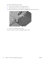
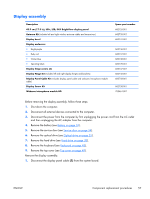
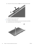
Display assembly Description 43.9 cm (17.3 in), HD+, LED, SVA BrightView display panel Antenna Kit (includes left and right wireless antenna cables and transceivers) Display bezel Display enclosure: ● Bright purple ● Ruby red ● Winter blue ● Sparkling black Display hinge covers (2) Display Hinge Kit (includes left and right display hinges and brackets) Display Panel Cable Kit (includes display panel cable and webcam/microphone module cable) Display Screw Kit Webcam/microphone module HD Spare part number 682755-001 682735-001 682741-001 682736-001 682737-001 682738-001 682739-001 682747-001 682746-001 682743-001 682758-001 703461-001 Before removing the display assembly, follow these steps: 1. Shut down the computer. 2. Disconnect all external devices connected to the computer. 3. Disconnect the power from the computer by first unplugging the power cord from the AC outlet and then unplugging the AC adapter from the computer. 4. Remove the battery (see Battery on page 33). 5. Remove the service door (see Service door on page 34). 6. Remove the optical drive (see Optical drive on page 35). 7. Remove the hard drive (see Hard drive on page 38). 8. Remove the keyboard (see Keyboard on page 45). 9. Remove the top cover (see Top cover on page 48). Remove the display assembly: 1. Disconnect the display panel cable (1) from the system board. ENWW Component replacement procedures 57
-
 1
1 -
2
-
3
-
4
-
5
-
6
-
7
-
8
-
9
-
10
-
11
-
12
-
13
-
14
-
15
-
16
-
17
-
18
-
19
-
20
-
21
-
22
-
23
-
24
-
25
-
26
-
27
-
28
-
29
-
30
-
31
-
32
-
33
-
34
-
35
-
36
-
37
-
38
-
39
-
40
-
41
-
42
-
43
-
44
-
45
-
46
-
47
-
48
-
49
-
50
-
51
-
52
-
53
-
54
-
55
-
56
-
57
-
58
-
59
-
 60
60 -
 61
61 -
 62
62 -
 63
63 -
 64
64 -
 65
65 -
 66
66 -
 67
67 -
 68
68 -
 69
69 -
 70
70 -
71
-
72
-
73
-
74
-
75
-
76
-
77
-
78
-
79
-
80
-
81
-
82
-
83
-
84
-
85
-
86
-
87
-
88
-
89
-
90
-
91
-
92
-
93
-
94
-
95
-
96
-
97
-
98
-
99
-
100
-
101
-
102
-
103
-
104
-
105
-
106
-
107
 |
 |
