HP Pavilion zx5000 Expansion Base - Maintenance and Service Guide
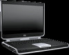
HP Pavilion zx5000 - Notebook PC Manual
 |
View all HP Pavilion zx5000 manuals
Add to My Manuals
Save this manual to your list of manuals |
HP Pavilion zx5000 manual content summary:
- HP Pavilion zx5000 | Expansion Base - Maintenance and Service Guide - Page 1
-001 January 2004 This guide is a troubleshooting reference used for maintaining and servicing the HP Notebook Expansion Base. It provides comprehensive information on identifying Expansion Base features, components, and spare parts; troubleshooting problems; and performing disassembly procedures - HP Pavilion zx5000 | Expansion Base - Maintenance and Service Guide - Page 2
statements accompanying such products and services. Nothing herein should be construed as constituting an additional warranty. HP shall not be liable for technical or editorial errors or omissions contained herein. Maintenance and Service Guide HP Notebook Expansion Base First Edition January - HP Pavilion zx5000 | Expansion Base - Maintenance and Service Guide - Page 3
1-10 2 Troubleshooting Before Replacing Parts 2-1 Problems and Solutions 2-2 3 Illustrated Parts Catalog 3.1 Serial Number Location 3-1 3.2 HP Notebook Expansion Base Major Components 3-2 4 Removal and Replacement Preliminaries 4.1 Tools Required 4-1 4.2 Service Considerations 4-1 Plastic - HP Pavilion zx5000 | Expansion Base - Maintenance and Service Guide - Page 4
10 Expansion Cable 5-17 5.11 Speaker Assembly 5-18 5.12 Front Case 5-20 6 Specifications A Connector Pin Assignments B Power Cord Set Requirements 3-Conductor Power Cord Set B-1 General Requirements B-1 Country-Specific Requirements B-2 C Screw Listing Index iv Maintenance and Service Guide - HP Pavilion zx5000 | Expansion Base - Maintenance and Service Guide - Page 5
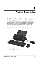
connectivity of HP Compaq Business Notebook nx9100 Series; HP Pavilion zd7000, zv5000, and zx5000 Series notebook PCs; and the Compaq Presario R3000 Series notebook PC. The Expansion Base provides an efficient, less-cluttered work environment, improved cable management, and wireless peripherals. It - HP Pavilion zx5000 | Expansion Base - Maintenance and Service Guide - Page 6
Product Description 1.1 Features ■ AC power (charges attached notebook while docked) ■ Supports panel sizes up to 17" wide ■ Altec Lansing speakers ■ Wireless keyboard ■ Wireless mouse ■ Wireless keyboard/mouse receiver ■ Security slots ■ Connectors: ❏ Expansion cable ❏ S/PDIF (Sony/Philips Digital - HP Pavilion zx5000 | Expansion Base - Maintenance and Service Guide - Page 7
Product Description 1.2 External Components The external components on the front panel of the Expansion Base are shown below and described in Table 1-2. Front components Maintenance and Service Guide 1-3 - HP Pavilion zx5000 | Expansion Base - Maintenance and Service Guide - Page 8
indicator light Function Connects the HP Notebook Expansion Base to the notebook computer. Produces stereo sound from the notebook. Lowers system volume. Mutes or restores volume. Increases system volume. Glows solid blue when the notebook is connected correctly. 1-4 Maintenance and Service Guide - HP Pavilion zx5000 | Expansion Base - Maintenance and Service Guide - Page 9
2 3 4 Component Audio out/Headphone jack USB connectors (3) Vent Kensington security cable slot Function Connects optional headphone or powered stereo speakers. Connect optional USB 2.0 devices do not prevent the product from being mishandled or stolen. Maintenance and Service Guide 1-5 - HP Pavilion zx5000 | Expansion Base - Maintenance and Service Guide - Page 10
Product Description The external components on the rear of the Expansion Base are shown below and described in Table 1-4. Rear components 1-6 Maintenance and Service Guide - HP Pavilion zx5000 | Expansion Base - Maintenance and Service Guide - Page 11
cable RJ-11 jack Vents (2) Function Connects the Expansion Base to a notebook computer. Connects a modem cable from the Expansion Base to a notebook. Allow airflow to Connects a serial device, such as a mouse. Connects AC power cord. Charges notebook while docked. Maintenance and Service Guide 1-7 - HP Pavilion zx5000 | Expansion Base - Maintenance and Service Guide - Page 12
not prevent the product from being mishandled or stolen. Allows airflow to cool internal components. Ä To prevent overheating, do not obstruct the vents. 1-8 Maintenance and Service Guide - HP Pavilion zx5000 | Expansion Base - Maintenance and Service Guide - Page 13
Wireless keyboard Receiver Wireless mouse Function Connects to the Expansion Base without a cable. Connects to a USB port on the Expansion Base. Allows connection between the Expansion Base and the wireless keyboard and mouse. Connects to the Expansion Base without a cable. Maintenance and Service - HP Pavilion zx5000 | Expansion Base - Maintenance and Service Guide - Page 14
by high external temperatures, system power consumption, power management/battery conservation configurations, and software To properly ventilate the HP Notebook Expansion Base, allow at least a 7.6-cm (3-inch) clearance on the left and right sides of the unit. 1-10 Maintenance and Service Guide - HP Pavilion zx5000 | Expansion Base - Maintenance and Service Guide - Page 15
Parts When troubleshooting a problem, check the following list for possible solutions before replacing parts: ■ Verify that cables are connected properly to the suspected defective part. ■ Verify that all required device drivers are installed on the notebook. Maintenance and Service Guide 2-1 - HP Pavilion zx5000 | Expansion Base - Maintenance and Service Guide - Page 16
Expansion Base is not plugged into an AC power outlet, draining the notebook battery pack. Plug the Expansion Base into an AC power outlet. If the above solution is unsuccessful, the power supply may be malfunctioning. Replace the power supply. (Section 5.6) 2-2 Maintenance and Service Guide - HP Pavilion zx5000 | Expansion Base - Maintenance and Service Guide - Page 17
Troubleshooting Table 2-2 External Device Problems and Solutions Problem Possible Cause Solution A new device is not recognized as part of the notebook system. The device cable or power cord is loose. ■ Test the device first by plugging it into the appropriate notebook connector. Note that - HP Pavilion zx5000 | Expansion Base - Maintenance and Service Guide - Page 18
or requesting information, provide the Expansion Base serial number and model number located on the bottom of the base plate. Serial number location Maintenance and Service Guide 3-1 - HP Pavilion zx5000 | Expansion Base - Maintenance and Service Guide - Page 19
Illustrated Parts Catalog 3.2 HP Notebook Expansion Base Major Components HP Notebook Expansion Base major components 3-2 Maintenance and Service Guide - HP Pavilion zx5000 | Expansion Base - Maintenance and Service Guide - Page 20
Illustrated Parts Catalog Table 3-1 Spare Parts: HP Notebook Expansion Base Major Components Item 1 2 3 4 5 6 7a 7b 7c 8 9 Kit (including the following components) Front case Rear cover Base enclosure Base plate Power supply and shield System board Spare Part Number 347433-001 347434-001 347435- - HP Pavilion zx5000 | Expansion Base - Maintenance and Service Guide - Page 21
Illustrated Parts Catalog HP Notebook Expansion Base miscellaneous components 3-4 Maintenance and Service Guide - HP Pavilion zx5000 | Expansion Base - Maintenance and Service Guide - Page 22
Illustrated Parts Catalog Table 3-1 Spare Parts: HP Notebook Expansion Base Miscellaneous Components Item 1 2 3 Description Receiver Wireless mouse Wireless keyboard ADP Australia Brazil Canada (Fr.) Czech -281 348086-141 348086-AB1 348086-031 348086-001 Maintenance and Service Guide 3-5 - HP Pavilion zx5000 | Expansion Base - Maintenance and Service Guide - Page 23
Illustrated Parts Catalog Table 3-2 Spare Parts: HP Notebook Expansion Base Miscellaneous Components (not illustrated) Item Description Power cord Australia Brazil Denmark Europe French Canada Israel India 345252-AD1 345252-AA1 345252-111 345252-031 345252-001 3-6 Maintenance and Service Guide - HP Pavilion zx5000 | Expansion Base - Maintenance and Service Guide - Page 24
provides essential information for proper and safe removal and replacement service. 4.1 Tools Required You will need the following tools to complete the removal Base, place the subassembly (and all accompanying screws) away from the work area to prevent damage. Maintenance and Service Guide 4-1 - HP Pavilion zx5000 | Expansion Base - Maintenance and Service Guide - Page 25
maintenance instructions. Cables and Connectors Cables must be handled with extreme care to avoid damage. Apply only the tension required to protection, but in many cases, the discharge contains enough power to alter device parameters or melt silicon junctions. A 4-2 Maintenance and Service Guide - HP Pavilion zx5000 | Expansion Base - Maintenance and Service Guide - Page 26
ground and that proper materials are selected to avoid static charging. When grounding is not possible, use an ionizer to dissipate electric charges. Maintenance and Service Guide 4-3 - HP Pavilion zx5000 | Expansion Base - Maintenance and Service Guide - Page 27
surface and use properly grounded tools and equipment. ■ Use conductive field service tools, such as cutters, screwdrivers, and vacuums. ■ When using leads, or circuitry. ■ Turn off power and input signals before inserting or removing connectors or test equipment. 4-4 Maintenance and Service Guide - HP Pavilion zx5000 | Expansion Base - Maintenance and Service Guide - Page 28
a minimum of one megohm ±10% resistance in the ground cords. To provide proper ground, wear a strap snugly against the cords of one megohm resistance ■ Static-dissipative tables or floor mats with hard ties to the ground ■ Field service kits ■ Static awareness labels Maintenance and Service Guide - HP Pavilion zx5000 | Expansion Base - Maintenance and Service Guide - Page 29
4-2 Static-Shielding Materials Material Antistatic plastic Carbon-loaded plastic Metallized laminate Use Bags Floor mats Floor mats Voltage Protection Level 1,500 V 7,500 V 5,000 V 4-6 Maintenance and Service Guide - HP Pavilion zx5000 | Expansion Base - Maintenance and Service Guide - Page 30
, that must be removed, replaced, and loosened when servicing the Expansion Base. Make special note of each screw size and location during removal and replacement. Refer to Appendix C, "Screw Listing," for detailed information on screw sizes, locations, and usage. Maintenance and Service Guide 5-1 - HP Pavilion zx5000 | Expansion Base - Maintenance and Service Guide - Page 31
Removal and Replacement Procedures 5.1 Serial Number Report the Expansion Base serial number to HP when requesting information or ordering spare parts. The serial number is located on the bottom of the Expansion Base. Serial number location 5-2 Maintenance and Service Guide - HP Pavilion zx5000 | Expansion Base - Maintenance and Service Guide - Page 32
Sequence Chart Description # of Screws Removed Preparing the Expansion Base for disassembly Base plate 4 Upper chassis 2 Power supply 5 System board 5 Front tray cover 4 Back panel 4 Expansion cable 4 Speaker assembly 2 Front case 6 Maintenance and Service Guide 5-3 - HP Pavilion zx5000 | Expansion Base - Maintenance and Service Guide - Page 33
the end of the expansion cable 1 to disconnect the cable from the notebook 2. 2. Disconnect the AC adapter and all external devices. ✎ The location of the expansion connector on the notebook may vary by notebook series and model. Disconnecting the expansion cable 5-4 Maintenance and Service Guide - HP Pavilion zx5000 | Expansion Base - Maintenance and Service Guide - Page 34
the Miscellaneous Plastics Kit 347436-001 1. Turn the Expansion Base upside down with the front facing away from you. 2. Remove the four PM2.5×17.0 screws 1 that secure the base plate to the base enclosure. 3. Remove the base plate 2. Removing the base plate Reverse the above procedure to install - HP Pavilion zx5000 | Expansion Base - Maintenance and Service Guide - Page 35
5.4). 3. Turn the Expansion Base right-side up with the rear panel facing you. 4. Remove the adhesive-backed 8.0-mm diameter screw covers 1. 5. Remove the two PM2.0×6.0 screws 2 that secure the rear cover to the base enclosure. Removing the rear cover screws 5-6 Maintenance and Service Guide - HP Pavilion zx5000 | Expansion Base - Maintenance and Service Guide - Page 36
Removal and Replacement Procedures 6. Lift the front edge of the rear cover up 1 until it disengages from the base enclosure. 7. Slide the rear cover toward you 2 and remove it. Removing the rear cover Maintenance and Service Guide 5-7 - HP Pavilion zx5000 | Expansion Base - Maintenance and Service Guide - Page 37
Removal and Replacement Procedures 8. Disconnect the following cables from the system board: 1 4-wire cable 2 2-wire RJ-11 modem cable 3 50-pin cable 4 6-wire cable 5 4-wire power cable Disconnecting the cables from the system board 5-8 Maintenance and Service Guide - HP Pavilion zx5000 | Expansion Base - Maintenance and Service Guide - Page 38
Removal and Replacement Procedures 9. Remove the two PM2.0×4.0 screws 1 that secure the upper chassis to the base enclosure. 10. Swing the top edge of the upper 3 and remove it. Removing the upper chassis Reverse the above procedure to install the upper chassis. Maintenance and Service Guide 5-9 - HP Pavilion zx5000 | Expansion Base - Maintenance and Service Guide - Page 39
5.5). 4. Turn the base enclosure upside down with the front facing you. 5. While holding the power supply in place with one hand underneath, remove the five PM2.0×6.0 screws that secure the power supply to the base enclosure. Removing the power supply screws 5-10 Maintenance and Service Guide - HP Pavilion zx5000 | Expansion Base - Maintenance and Service Guide - Page 40
. 8. Lift the power supply and shield approximately one inch 2. 9. While holding the power supply and shield, remove the power connector 3 from the supports in the base enclosure. Removing the power supply Reverse the above procedure to install the power supply. Maintenance and Service Guide 5-11 - HP Pavilion zx5000 | Expansion Base - Maintenance and Service Guide - Page 41
panel facing you. 6. Remove the three PM2.0×6.0 screws 1 that secure the system board to the base enclosure. 7. Use a 5.0-mm hex socket to remove the two HM5.0x9.0 standoffs 2 on either side of the serial connector. Removing the system board screws and standoffs 5-12 Maintenance and Service Guide - HP Pavilion zx5000 | Expansion Base - Maintenance and Service Guide - Page 42
base enclosure. 9. Remove the system board from the base enclosure 4. Removing the system board Reverse the above procedure to install the system board. Maintenance and Service Guide 5-13 - HP Pavilion zx5000 | Expansion Base - Maintenance and Service Guide - Page 43
you. 5. Cut all tie-wraps 1 that bundle the Expansion Base cables and secure the RJ-11 modem cable to the chassis. 6. Remove the four PM2.0×4.0 screws 2 that secure the front tray cover to the chassis. Removing the front tray cover screws 5-14 Maintenance and Service Guide - HP Pavilion zx5000 | Expansion Base - Maintenance and Service Guide - Page 44
and then away from you to remove it. Removing the front tray cover Reverse the above procedure to install the front tray cover. Maintenance and Service Guide 5-15 - HP Pavilion zx5000 | Expansion Base - Maintenance and Service Guide - Page 45
before performing the following steps. 6. Remove the four PM2.0×4.0 screws 1 that secure the back panel to the chassis. 7. Remove the back panel with the RJ-11 cable attached 2. Removing the back panel Reverse the above procedure to install the back panel. 5-16 Maintenance and Service Guide - HP Pavilion zx5000 | Expansion Base - Maintenance and Service Guide - Page 46
up with the rear facing you. Rotate the chassis so that the expansion cable connector is facing away from you. 7. Remove the four PM2.0×2.0 screws 1 that secure the expansion cable clamps to the chassis. 8. Remove the expansion cable clamps 2 and the expansion cable 3. Removing the expansion cable - HP Pavilion zx5000 | Expansion Base - Maintenance and Service Guide - Page 47
down. 6. Remove the 6-wire audio control cable 1 and the 4-wire speaker cable 2 from the chassis hole through which they are routed. 7. Remove the two PM2.0×4.0 screws 3 that secure the speaker assembly to the chassis. Removing the speaker assembly screws 5-18 Maintenance and Service Guide - HP Pavilion zx5000 | Expansion Base - Maintenance and Service Guide - Page 48
of the speaker assembly to remove it from the chassis 2. Removing the speaker assembly Reverse the above procedure to install the speaker assembly. Maintenance and Service Guide 5-19 - HP Pavilion zx5000 | Expansion Base - Maintenance and Service Guide - Page 49
(Section 5.11). 6. Turn the chassis right-side up with the rear facing you. Rotate the top of the chassis toward you. 7. Remove the six PM2.0×5.0 screws 1 that secure the upper chassis front case to the chassis. 8. Slide the front case toward you 2 to disengage it from the chassis. 9. Remove the - HP Pavilion zx5000 | Expansion Base - Maintenance and Service Guide - Page 50
specifications. Table 6-1 HP Notebook Expansion Base Dimensions Height Width Depth 22.8 cm 31.8 cm 29.8 cm Weight 3.5 kg Stand-alone power requirements Power safety standards specify thermal limits for plastic surfaces. The notebook operates well within this range of temperatures. Relative - HP Pavilion zx5000 | Expansion Base - Maintenance and Service Guide - Page 51
Specifications Power supply Rated input voltage Rated input current Rated frequency Table 6-2 Internal AC Adapter 160 W with PFC 100 to 240 VAC RMS 1.7 A RMS 47 to 63 Hz 6-2 Maintenance and Service Guide - HP Pavilion zx5000 | Expansion Base - Maintenance and Service Guide - Page 52
A Connector Pin Assignments Table A-1 RJ-45 Network Interface Pin Signal 1 Transmit + 2 Transmit - 3 Receive + 4 Unused Pin Signal 5 Unused 6 Receive - 7 Unused 8 Unused Maintenance and Service Guide A-1 - HP Pavilion zx5000 | Expansion Base - Maintenance and Service Guide - Page 53
Connector Pin Assignments Table A-2 RJ-11 Modem Pin Signal 1 Unused 2 Tip 3 Ring Pin Signal 4 Unused 5 Unused 6 Unused Table A-3 Universal Serial Bus Pin Signal 1 +5 VDC 2 Data - Pin Signal 3 Data + 4 Ground A-2 Maintenance and Service Guide - HP Pavilion zx5000 | Expansion Base - Maintenance and Service Guide - Page 54
Pin Signal 1 Ground (Y) 2 Ground (C) Connector Pin Assignments Table A-4 S-Video 43 2 1 Pin Signal 3 Y-Luminance (Intensity) 4 C-Chrominance (Color) Table A-5 Audio Line-Out Pin Signal 1 Audio out Pin Signal 2 Ground Maintenance and Service Guide A-3 - HP Pavilion zx5000 | Expansion Base - Maintenance and Service Guide - Page 55
Connector Pin Assignments Table A-6 Serial Pin Signal 1 Carrier detect 2 Receive data 3 Transmit data 4 Data terminal ready 5 Ground Pin Signal 6 Data set ready 7 Ready to send 8 Clear to send 9 Ring indicator A-4 Maintenance and Service Guide - HP Pavilion zx5000 | Expansion Base - Maintenance and Service Guide - Page 56
Connector Pin Assignments Table A-7 S/PDIF Audio Line-Out 1 2 Pin Signal 1 Audio signal Pin Signal 2 Ground/return Table A-8 Video 1 Pin Signal 1 Video signal 2 Pin Signal 2 Ground/return Maintenance and Service Guide A-5 - HP Pavilion zx5000 | Expansion Base - Maintenance and Service Guide - Page 57
voltage rating of 125 or 250 volts AC, as required by each country's power system. ■ The appliance coupler must meet the mechanical configuration of an EN 60 320/IEC 320 Standard Sheet C13 connector for mating with the appliance inlet on the back of the notebook. Maintenance and Service Guide B-1 - HP Pavilion zx5000 | Expansion Base - Maintenance and Service Guide - Page 58
Power Cord Set Requirements Country-Specific Requirements 3-Conductor Power Cord Set Requirements Country Australia Austria Belgium Canada Denmark Finland France Germany Italy Japan METI KEMA NEMKO SEMKO SEV Applicable Note Number 1 1 1 2 1 1 1 1 1 3 1 1 1 1 B-2 Maintenance and Service Guide - HP Pavilion zx5000 | Expansion Base - Maintenance and Service Guide - Page 59
Power Cord Set Requirements 3-Conductor Power Cord Set Requirements (Continued) Country United Kingdom United States Notes Accredited Agency BSI UL Applicable Note Number 1 2 1. The flexible cord must be Type HO5VV-F, 3-conductor, 1.0 mm² conductor size. Power cord cord, and cord - HP Pavilion zx5000 | Expansion Base - Maintenance and Service Guide - Page 60
C Screw Listing This appendix provides specification and reference information for the screws used in the HP Notebook Expansion Base. All screws listed in this appendix are available in the Miscellaneous Screw Kit, spare part number 347439-001. Maintenance and Service Guide C-1 - HP Pavilion zx5000 | Expansion Base - Maintenance and Service Guide - Page 61
Screw Listing Table C-1 Phillips PM2.5×17.0 Screw mm Color Qty. Length Thread Bronze 4 17.0 mm 2.5 mm Where used: Four screws that secure the base plate to the base enclosure (documented in Section 5.4) Head Width 6.0 mm Phillips M2.5×17.0 screw locations C-2 Maintenance and Service Guide - HP Pavilion zx5000 | Expansion Base - Maintenance and Service Guide - Page 62
Screw Listing Table C-2 Phillips PM2.0×6.0 Screw mm Color Qty. Length Thread Bronze 10 6.0 mm 2.0 mm Where used: Five screws that secure the power supply to the base enclosure (documented in Section 5.6) Head Width 4.5 mm Phillips M2.0×6.0 screw locations Maintenance and Service Guide C-3 - HP Pavilion zx5000 | Expansion Base - Maintenance and Service Guide - Page 63
Table C-2 Phillips PM2.0×6.0 Screw (Continued) mm Color Qty. Length Thread Bronze 10 6.0 mm 2.0 mm Where used: Two screws that secure the rear cover to the base enclosure (documented in Section 5.5) Head Width 4.5 mm Phillips M2.0×6.0 screw locations C-4 Maintenance and Service Guide - HP Pavilion zx5000 | Expansion Base - Maintenance and Service Guide - Page 64
Table C-2 Phillips PM2.0×6.0 Screw (Continued) mm Color Qty. Length Thread Bronze 10 6.0 mm 2.0 mm Where used: Three screws that secure the system board to the base enclosure (documented in Section 5.7) Head Width 4.5 mm Phillips M2.0×6.0 screw locations Maintenance and Service Guide C-5 - HP Pavilion zx5000 | Expansion Base - Maintenance and Service Guide - Page 65
Screw Listing Table C-4 HM5.0×9.0 Standoff mm Color Qty. Length Thread Silver 2 9.0 mm 5.0 mm Where used: Two standoffs that secure the system board to the base enclosure (documented in Section 5.7) Head Width 5.0 mm HM5.0×9.0 screw locations C-6 Maintenance and Service Guide - HP Pavilion zx5000 | Expansion Base - Maintenance and Service Guide - Page 66
Screw Listing Table C-5 Phillips PM2.0×4.0 Screw mm Color Qty. Length Thread Bronze 18 4.0 mm 2.0 mm Where used: Two screws that secure the upper chassis to the base enclosure (documented in Section 5.5) Head Width 4.0 mm Phillips M2.0×4.0 screw locations Maintenance and Service Guide C-7 - HP Pavilion zx5000 | Expansion Base - Maintenance and Service Guide - Page 67
Table C-5 Phillips PM2.0x4.0 Screw (Continued) mm Color Qty. Length Thread Bronze 18 4.0 mm 2.0 mm Where used: Four screws that secure the front tray cover to the upper chassis (documented in Section 5.8) Head Width 4.0 mm Phillips M2.0x4.0 screw locations C-8 Maintenance and Service Guide - HP Pavilion zx5000 | Expansion Base - Maintenance and Service Guide - Page 68
Screw Listing Table C-5 Phillips PM2.0×4.0 Screw (Continued) mm Color Qty. Length Bronze 18 4.0 mm Where used: Four screws that secure the back panel to the chassis (documented in Section 5.9) Thread 2.0 mm Head Width 4.0 mm Phillips M2.0x4.0 screw locations Maintenance and Service Guide - HP Pavilion zx5000 | Expansion Base - Maintenance and Service Guide - Page 69
Table C-5 Phillips PM2.0×4.0 Screw (Continued) mm Color Qty. Length Thread Bronze 18 4.0 mm 2.0 mm Where used: Two screws that secure the speaker assembly to the chassis (documented in Section 5.11) Head Width 4.0 mm Phillips M2.0x4.0 screw locations C-10 Maintenance and Service Guide - HP Pavilion zx5000 | Expansion Base - Maintenance and Service Guide - Page 70
Screw Listing Table C-5 Phillips PM2.0×4.0 Screw (Continued) mm Color Qty. Length Bronze 18 4.0 mm Where used: Six screws that secure the front case to the chassis (documented in Section 5.12) Thread 2.0 mm Head Width 4.0 mm Phillips M2.0x4.0 screw locations Maintenance and Service Guide - HP Pavilion zx5000 | Expansion Base - Maintenance and Service Guide - Page 71
Listing Table C-6 Phillips PM2.0×2.0 Screw Head mm Color Qty. Length Thread Width Silver 4 2.0 mm 2.0 mm 8 mm Where used: Four screws that secure the expansion cable brackets to the chassis (documented in Section 5.10) Phillips M2.0x2.0 screw locations C-12 Maintenance and Service Guide - HP Pavilion zx5000 | Expansion Base - Maintenance and Service Guide - Page 72
Index A AC adapter specifications 6-2 audio line-out pin assignments A-3 B back panel removal 5-16 spare part number 3-3 base enclosure, spare part number 3-3 base plate removal 5-5 spare part number 3-3 C cables, service considerations 4-2 components front 1-3 left-side 1-5 rear 1-5 right-side - HP Pavilion zx5000 | Expansion Base - Maintenance and Service Guide - Page 73
-out jack pin assignments A-5 S/PDIF connector location 1-7 screw listing C-1 security cable slot 1-5, 1-8 serial connector location 1-7 pin assignments A-4 serial number 3-1, 5-2 service considerations 4-1 speaker assembly location 1-4 removal 5-18 spare part number 3-3 specifications AC adapter - HP Pavilion zx5000 | Expansion Base - Maintenance and Service Guide - Page 74
4-3 troubleshooting 2-1 problems and solutions 2-2 TV out, location 1-7 U upper chassis removal 5-6 spare part number 3-3 USB connectors location 1-5, 1-7 pin assignments A-2 V vent 1-5, 1-7, 1-8 volume down button 1-4 volume up button 1-4 W wireless accessories 1-9 wireless keyboard 1-9 spare
-
 1
1 -
 2
2 -
 3
3 -
 4
4 -
 5
5 -
 6
6 -
 7
7 -
8
-
9
-
10
-
11
-
12
-
13
-
14
-
15
-
16
-
17
-
18
-
19
-
20
-
21
-
22
-
23
-
24
-
25
-
26
-
27
-
28
-
29
-
30
-
31
-
32
-
33
-
34
-
35
-
36
-
37
-
38
-
39
-
40
-
41
-
42
-
43
-
44
-
45
-
46
-
47
-
48
-
49
-
50
-
51
-
52
-
53
-
54
-
55
-
56
-
57
-
58
-
59
-
60
-
61
-
62
-
63
-
64
-
65
-
66
-
67
-
68
-
69
-
70
-
71
-
72
-
73
-
74
 |
 |

Maintenance and Service
Guide
HP Notebook Expansion Base
Document Part Number: 344524-001
January 2004
This guide is a troubleshooting reference used for maintaining
and servicing the HP Notebook Expansion Base. It provides
comprehensive information on identifying Expansion Base
features, components, and spare parts; troubleshooting problems;
and performing disassembly procedures.