HP Presario A900 Compaq Presario A900 Notebook PC - Maintenance and Service Gu - Page 44
from the camera module., as far from the display enclosure as the camera module cable allows.
 |
View all HP Presario A900 manuals
Add to My Manuals
Save this manual to your list of manuals |
Page 44 highlights
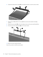
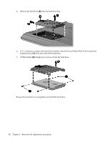
6. Separate the display bezel top edge (3) from the display assembly to access the camera module. 7. Remove the two Philllips PM2.0×3.0 screws (1) that secure the camera module to the display enclosure. 8. Release the camera module (2) as far from the display enclosure as the camera module cable allows. 9. Disconnect the camera module cable (3) from the camera module. 10. Remove the camera module and bracket. Reverse this procedure to install the camera module. 36 Chapter 4 Removal and replacement procedures
-
 1
1 -
2
-
3
-
4
-
5
-
6
-
7
-
8
-
9
-
10
-
11
-
12
-
13
-
14
-
15
-
16
-
17
-
18
-
19
-
20
-
21
-
22
-
23
-
24
-
25
-
26
-
27
-
28
-
29
-
30
-
31
-
32
-
33
-
34
-
35
-
36
-
37
-
38
-
 39
39 -
 40
40 -
 41
41 -
 42
42 -
 43
43 -
 44
44 -
 45
45 -
 46
46 -
 47
47 -
 48
48 -
 49
49 -
50
-
51
-
52
-
53
-
54
-
55
-
56
-
57
-
58
-
59
-
60
-
61
-
62
-
63
-
64
-
65
-
66
-
67
-
68
-
69
-
70
-
71
-
72
-
73
-
74
-
75
-
76
-
77
-
78
-
79
-
80
-
81
-
82
-
83
-
84
-
85
-
86
-
87
-
88
-
89
-
90
-
91
-
92
-
93
-
94
-
95
-
96
-
97
-
98
-
99
-
100
-
101
-
102
-
103
-
104
-
105
-
106
-
107
-
108
-
109
-
110
-
111
-
112
-
113
-
114
-
115
-
116
-
117
-
118
-
119
-
120
-
121
-
122
-
123
-
124
-
125
-
126
-
127
-
128
-
129
 |
 |

6
.
Separate the display bezel top edge
(3)
from the display assembly to access the camera module.
7
.
Remove the two Philllips PM2.0×3.0 screws
(1)
that secure the camera module to the display
enclosure.
8
.
Release the camera module
(2)
as far from the display enclosure as the camera module cable allows.
9
.
Disconnect the camera module cable
(3)
from the camera module.
10
.
Remove the camera module and bracket.
Reverse this procedure to install the camera module.
36
Chapter
4
Removal and replacement procedures