HP Presario A900 Compaq Presario A900 Notebook PC - Maintenance and Service Gu - Page 52
Optical drive, Remove the Phillips PM2.5×9.0 screw
 |
View all HP Presario A900 manuals
Add to My Manuals
Save this manual to your list of manuals |
Page 52 highlights
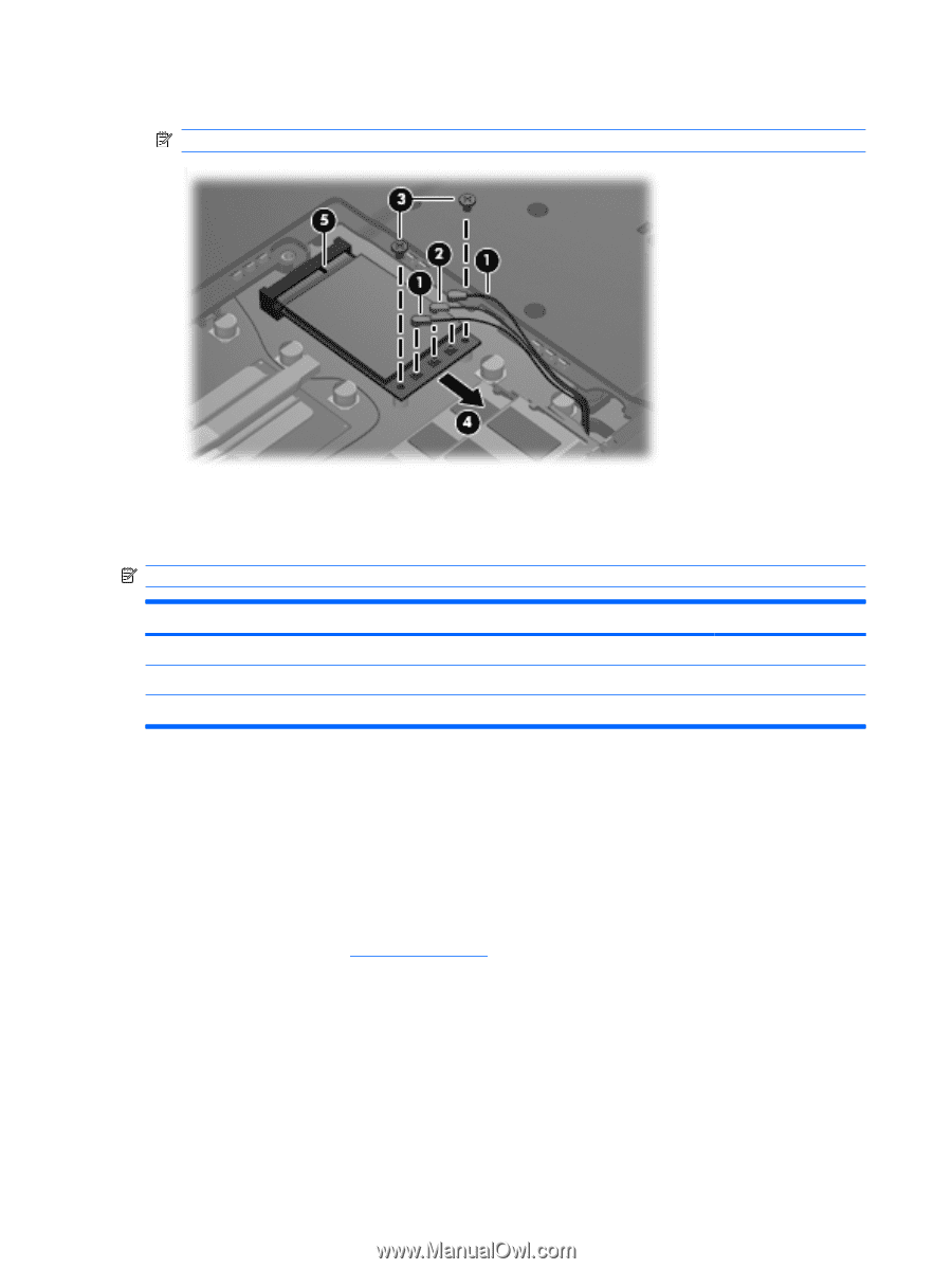
5. Remove the WLAN module (4) by pulling the module away from the slot at an angle. NOTE: WLAN modules are designed with a notch (5) to prevent incorrect installation. Reverse this procedure to install the WLAN module. Optical drive NOTE: All optical drive spare part kits include an optical drive bezel and optical drive bracket. Description Spare part number DVD±RW and CD-RW Super Multi Double-Layer Combo Drive with LightScribe 462336-001 DVD±RW and CD-RW Super Multi Double-Layer Combo Drive 462335-001 Optical Drive Bezel/Bracket Kit (includes optical drive bezel and optical drive bracket and screws) 462334-001 Before removing the optical drive, follow these steps: 1. Shut down the computer. If you are unsure whether the computer is off or in Hibernation, turn the computer on, and then shut it down through the operating system. 2. Disconnect all external devices connected to the computer. 3. Disconnect the power from the computer by first unplugging the power cord from the AC outlet and then unplugging the AC adapter from the computer. 4. Remove the battery (see Battery on page 34). Remove the optical drive: 1. Position the computer with the left side toward you. 2. Remove the Phillips PM2.5×9.0 screw (1) that secures the optical drive to the computer. 3. Insert a thin tool, such as a paper clip (2), into the release access. (The optical drive disc tray is partially ejected from the optical drive.) 44 Chapter 4 Removal and replacement procedures
-
 1
1 -
2
-
3
-
4
-
5
-
6
-
7
-
8
-
9
-
10
-
11
-
12
-
13
-
14
-
15
-
16
-
17
-
18
-
19
-
20
-
21
-
22
-
23
-
24
-
25
-
26
-
27
-
28
-
29
-
30
-
31
-
32
-
33
-
34
-
35
-
36
-
37
-
38
-
39
-
40
-
41
-
42
-
43
-
44
-
45
-
46
-
 47
47 -
 48
48 -
 49
49 -
 50
50 -
 51
51 -
 52
52 -
 53
53 -
 54
54 -
 55
55 -
 56
56 -
 57
57 -
58
-
59
-
60
-
61
-
62
-
63
-
64
-
65
-
66
-
67
-
68
-
69
-
70
-
71
-
72
-
73
-
74
-
75
-
76
-
77
-
78
-
79
-
80
-
81
-
82
-
83
-
84
-
85
-
86
-
87
-
88
-
89
-
90
-
91
-
92
-
93
-
94
-
95
-
96
-
97
-
98
-
99
-
100
-
101
-
102
-
103
-
104
-
105
-
106
-
107
-
108
-
109
-
110
-
111
-
112
-
113
-
114
-
115
-
116
-
117
-
118
-
119
-
120
-
121
-
122
-
123
-
124
-
125
-
126
-
127
-
128
-
129
 |
 |