HP Presario CQ61-200 Compaq Presario CQ61 Notebook PC and HP G61 Notebook PC - - Page 83
that services the processor, the fan/heat sink assembly
 |
View all HP Presario CQ61-200 manuals
Add to My Manuals
Save this manual to your list of manuals |
Page 83 highlights
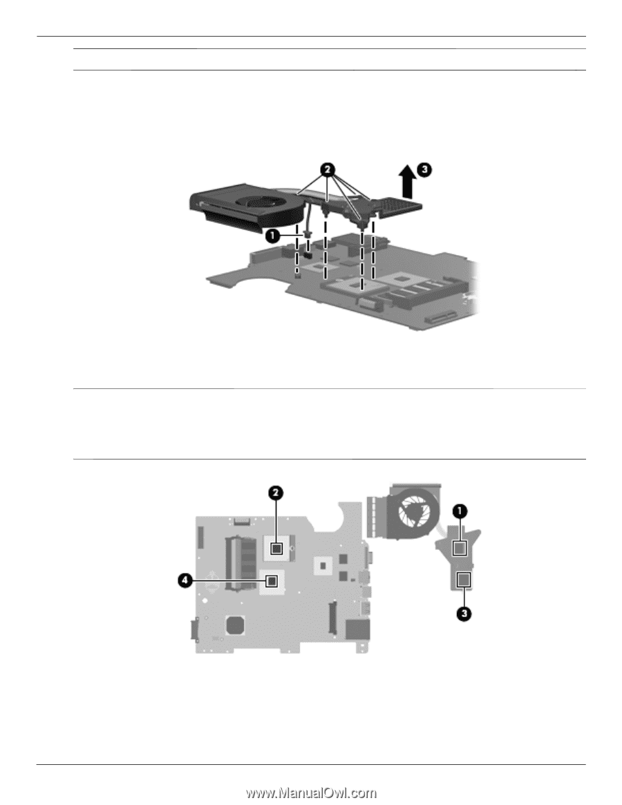
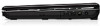
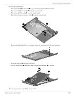
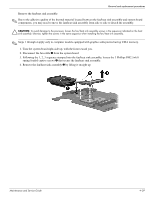
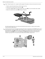
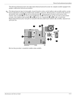
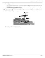
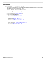
Removal and replacement procedures ✎ Steps 5 through 8 apply only to computer models equipped with graphics subsystems having discrete memory. 5. Turn the system board right-side up, with the front toward you. 6. Disconnect the fan cable from the system board 1. 7. Loosen the 5 Phillips PM2.5×6.0 spring-loaded captive screws 2 that secure the fan/heat sink assembly. 8. Remove the fan/heat sink assembly 3 by lifting it straight up. The following illustration shows the replacement thermal material locations for computer models graphics subsystems having UMA memory ✎ The thermal material must be thoroughly cleaned from the surfaces of the fan/heat sink assembly and the system board components each time the fan/heat sink assembly is removed. Thermal grease is located on the section of the fan/heat sink assembly 1 that services the processor 2. A thermal pad is located on the section of the fan/heat sink assembly 3 that services the Northbridge chip 4. Replacement thermal grease and pads are included in spare parts kits for all system boards, fan/heat sink assemblies, and processors. 4-40 Maintenance and Service Guide
-
 1
1 -
2
-
3
-
4
-
5
-
6
-
7
-
8
-
9
-
10
-
11
-
12
-
13
-
14
-
15
-
16
-
17
-
18
-
19
-
20
-
21
-
22
-
23
-
24
-
25
-
26
-
27
-
28
-
29
-
30
-
31
-
32
-
33
-
34
-
35
-
36
-
37
-
38
-
39
-
40
-
41
-
42
-
43
-
44
-
45
-
46
-
47
-
48
-
49
-
50
-
51
-
52
-
53
-
54
-
55
-
56
-
57
-
58
-
59
-
60
-
61
-
62
-
63
-
64
-
65
-
66
-
67
-
68
-
69
-
70
-
71
-
72
-
73
-
74
-
75
-
76
-
77
-
 78
78 -
 79
79 -
 80
80 -
 81
81 -
 82
82 -
 83
83 -
 84
84 -
 85
85 -
 86
86 -
 87
87 -
 88
88 -
89
-
90
-
91
-
92
-
93
-
94
-
95
-
96
-
97
-
98
-
99
-
100
-
101
-
102
-
103
-
104
-
105
-
106
-
107
-
108
-
109
-
110
-
111
-
112
-
113
-
114
-
115
-
116
-
117
-
118
-
119
-
120
-
121
-
122
-
123
-
124
-
125
-
126
-
127
-
128
-
129
-
130
-
131
-
132
-
133
-
134
-
135
-
136
-
137
 |
 |