HP Presario V3000 Compaq Presario V3000 Notebook PC Maintenance and Service Gu - Page 113
Description, of Screws Removed
 |
View all HP Presario V3000 manuals
Add to My Manuals
Save this manual to your list of manuals |
Page 113 highlights
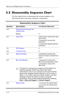
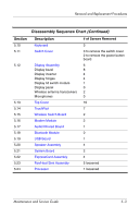
Removal and Replacement Procedures Disassembly Sequence Chart (Continued) Section 5.10 5.11 5.12 5.13 5.14 5.15 5.16 5.17 5.18 5.19 5.20 5.21 5.22 5.23 5.24 Description Keyboard Switch Cover Display Assembly Display bezel Display inverter Display hinges Display lid switch module Display panel Wireless antenna transceivers Microphones Top Cover TouchPad Wireless Switch Board Modem Module Audio/Infrared Board Bluetooth Module USB Board Speaker Assembly System Board ExpressCard Assembly Fan/Heat Sink Assembly Processor # of Screws Removed 3 3 to remove the switch cover 2 to remove the power button board 6 8 4 4 1 0 2 0 16 7 2 2 1 0 1 4 2 4 5 loosened 1 loosened Maintenance and Service Guide 5-3
-
 1
1 -
2
-
3
-
4
-
5
-
6
-
7
-
8
-
9
-
10
-
11
-
12
-
13
-
14
-
15
-
16
-
17
-
18
-
19
-
20
-
21
-
22
-
23
-
24
-
25
-
26
-
27
-
28
-
29
-
30
-
31
-
32
-
33
-
34
-
35
-
36
-
37
-
38
-
39
-
40
-
41
-
42
-
43
-
44
-
45
-
46
-
47
-
48
-
49
-
50
-
51
-
52
-
53
-
54
-
55
-
56
-
57
-
58
-
59
-
60
-
61
-
62
-
63
-
64
-
65
-
66
-
67
-
68
-
69
-
70
-
71
-
72
-
73
-
74
-
75
-
76
-
77
-
78
-
79
-
80
-
81
-
82
-
83
-
84
-
85
-
86
-
87
-
88
-
89
-
90
-
91
-
92
-
93
-
94
-
95
-
96
-
97
-
98
-
99
-
100
-
101
-
102
-
103
-
104
-
105
-
106
-
107
-
 108
108 -
 109
109 -
 110
110 -
 111
111 -
 112
112 -
 113
113 -
 114
114 -
 115
115 -
 116
116 -
 117
117 -
 118
118 -
119
-
120
-
121
-
122
-
123
-
124
-
125
-
126
-
127
-
128
-
129
-
130
-
131
-
132
-
133
-
134
-
135
-
136
-
137
-
138
-
139
-
140
-
141
-
142
-
143
-
144
-
145
-
146
-
147
-
148
-
149
-
150
-
151
-
152
-
153
-
154
-
155
-
156
-
157
-
158
-
159
-
160
-
161
-
162
-
163
-
164
-
165
-
166
-
167
-
168
-
169
-
170
-
171
-
172
-
173
-
174
-
175
-
176
-
177
-
178
-
179
-
180
-
181
-
182
-
183
-
184
-
185
-
186
-
187
-
188
-
189
-
190
-
191
-
192
-
193
-
194
-
195
-
196
-
197
-
198
-
199
-
200
-
201
-
202
-
203
-
204
-
205
-
206
-
207
-
208
-
209
-
210
-
211
-
212
-
213
-
214
-
215
-
216
-
217
-
218
-
219
-
220
-
221
-
222
-
223
-
224
-
225
-
226
-
227
-
228
-
229
-
230
-
231
-
232
-
233
-
234
-
235
-
236
-
237
-
238
-
239
-
240
-
241
-
242
-
243
-
244
-
245
-
246
-
247
-
248
-
249
-
250
-
251
-
252
-
253
-
254
-
255
-
256
-
257
-
258
-
259
-
260
-
261
-
262
-
263
-
264
-
265
-
266
-
267
-
268
-
269
-
270
-
271
-
272
-
273
-
274
-
275
-
276
-
277
-
278
-
279
-
280
-
281
-
282
-
283
-
284
-
285
-
286
-
287
-
288
-
289
-
290
-
291
-
292
-
293
-
294
-
295
-
296
-
297
-
298
 |
 |
Removal and Replacement Procedures
Maintenance and Service Guide
5°3
Section
Description
# of Screws Removed
5.10
Keyboard
3
5.11
Switch Cover
3 to remove the switch cover
2 to remove the power button
board
5.12
Display Assembly
Display bezel
Display inverter
Display hinges
Display lid switch module
Display panel
Wireless antenna transceivers
Microphones
6
8
4
4
1
0
2
0
5.13
Top Cover
16
5.14
TouchPad
7
5.15
Wireless Switch Board
2
5.16
Modem Module
2
5.17
Audio/Infrared Board
1
5.18
Bluetooth Module
0
5.19
USB Board
1
5.20
Speaker Assembly
4
5.21
System Board
2
5.22
ExpressCard Assembly
4
5.23
Fan/Heat Sink Assembly
5 loosened
5.24
Processor
1 loosened
Disassembly Sequence Chart
(Continued)