HP Presario V6100 Compaq Presario V6000 Notebook PC Maintenance and Service Gu - Page 139
Remove the Phillips PM2.0×3.0 screw, num lock board to the switch cover and remove the num lock
 |
View all HP Presario V6100 manuals
Add to My Manuals
Save this manual to your list of manuals |
Page 139 highlights
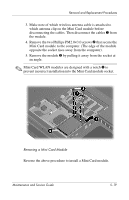
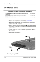
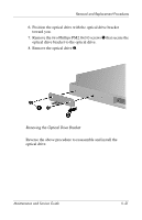
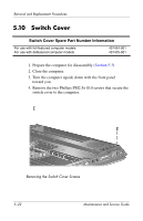
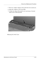
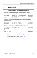
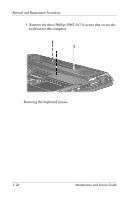
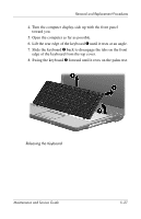
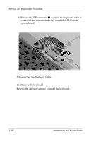
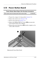
Removal and Replacement Procedures 8. Release the zero insertion force (ZIF) connector 1 to which the LED board cable is connected and disconnect the cable 2 from the LED board. 9. If it is necessary to replace the num lock board, disconnect the num lock board cable 3 from the LED board. 10. Remove the Phillips PM2.0×3.0 screw 4 that secures the num lock board to the switch cover and remove the num lock board 5. 11. Remove the switch cover. Removing the Num Lock Board Reverse the above procedure to install the switch cover and num lock board. 5-24 Maintenance and Service Guide
-
 1
1 -
2
-
3
-
4
-
5
-
6
-
7
-
8
-
9
-
10
-
11
-
12
-
13
-
14
-
15
-
16
-
17
-
18
-
19
-
20
-
21
-
22
-
23
-
24
-
25
-
26
-
27
-
28
-
29
-
30
-
31
-
32
-
33
-
34
-
35
-
36
-
37
-
38
-
39
-
40
-
41
-
42
-
43
-
44
-
45
-
46
-
47
-
48
-
49
-
50
-
51
-
52
-
53
-
54
-
55
-
56
-
57
-
58
-
59
-
60
-
61
-
62
-
63
-
64
-
65
-
66
-
67
-
68
-
69
-
70
-
71
-
72
-
73
-
74
-
75
-
76
-
77
-
78
-
79
-
80
-
81
-
82
-
83
-
84
-
85
-
86
-
87
-
88
-
89
-
90
-
91
-
92
-
93
-
94
-
95
-
96
-
97
-
98
-
99
-
100
-
101
-
102
-
103
-
104
-
105
-
106
-
107
-
108
-
109
-
110
-
111
-
112
-
113
-
114
-
115
-
116
-
117
-
118
-
119
-
120
-
121
-
122
-
123
-
124
-
125
-
126
-
127
-
128
-
129
-
130
-
131
-
132
-
133
-
 134
134 -
 135
135 -
 136
136 -
 137
137 -
 138
138 -
 139
139 -
 140
140 -
 141
141 -
 142
142 -
 143
143 -
 144
144 -
145
-
146
-
147
-
148
-
149
-
150
-
151
-
152
-
153
-
154
-
155
-
156
-
157
-
158
-
159
-
160
-
161
-
162
-
163
-
164
-
165
-
166
-
167
-
168
-
169
-
170
-
171
-
172
-
173
-
174
-
175
-
176
-
177
-
178
-
179
-
180
-
181
-
182
-
183
-
184
-
185
-
186
-
187
-
188
-
189
-
190
-
191
-
192
-
193
-
194
-
195
-
196
-
197
-
198
-
199
-
200
-
201
-
202
-
203
-
204
-
205
-
206
-
207
-
208
-
209
-
210
-
211
-
212
-
213
-
214
-
215
-
216
-
217
-
218
-
219
-
220
-
221
-
222
-
223
-
224
-
225
-
226
-
227
-
228
-
229
-
230
-
231
-
232
-
233
-
234
-
235
-
236
-
237
-
238
-
239
-
240
-
241
-
242
-
243
-
244
-
245
-
246
-
247
-
248
-
249
-
250
-
251
-
252
-
253
-
254
-
255
-
256
-
257
-
258
-
259
-
260
-
261
-
262
-
263
-
264
-
265
-
266
-
267
-
268
-
269
-
270
-
271
-
272
-
273
-
274
-
275
-
276
-
277
-
278
 |
 |

5–24
Maintenance and Service Guide
Removal and Replacement Procedures
8. Release the zero insertion force (ZIF) connector
1
to which
the LED board cable is connected and disconnect the cable
2
from the LED board.
9. If it is necessary to replace the num lock board, disconnect
the num lock board cable
3
from the LED board.
10. Remove the Phillips PM2.0×3.0 screw
4
that secures the
num lock board to the switch cover and remove the num lock
board
5
.
11. Remove the switch cover.
Removing the Num Lock Board
Reverse the above procedure to install the switch cover and num
lock board.