HP ProBook 4520s HP ProBook 4520s Notebook PC and HP ProBook 4720s Notebook PC - Page 75
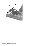
The black WLAN antenna cable is connected to the WLAN module Main terminal.
 |
View all HP ProBook 4520s manuals
Add to My Manuals
Save this manual to your list of manuals |
Page 75 highlights
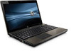
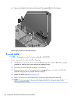
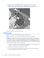
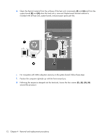
Before removing the WLAN module, follow these steps: 1. Shut down the computer. If you are unsure whether the computer is off or in Hibernation, turn the computer on, and then shut it down through the operating system. 2. Disconnect all external devices connected to the computer. 3. Disconnect the power from the computer by first unplugging the power cord from the AC outlet and then unplugging the AC adapter from the computer. 4. Remove the battery (see Battery on page 50). 5. Remove the following components: a. Switch cover and keyboard (see Switch cover and keyboard on page 51) b. Thermal shield (see Thermal shield on page 62) Remove the WLAN module: 1. Position the computer right-side up with the front toward you. 2. Disconnect the WLAN antenna cables (1) from the terminals on the WLAN module. NOTE: The black WLAN antenna cable is connected to the WLAN module "Main" terminal. The white WLAN antenna cable is connected to the WLAN module "Aux" terminal. 3. Remove the two Phillips PM2.0×4.0 screws (2) that secure the WLAN module to the computer. (The edge of the module opposite the slot rises away from the computer.) Component replacement procedures 67
-
 1
1 -
2
-
3
-
4
-
5
-
6
-
7
-
8
-
9
-
10
-
11
-
12
-
13
-
14
-
15
-
16
-
17
-
18
-
19
-
20
-
21
-
22
-
23
-
24
-
25
-
26
-
27
-
28
-
29
-
30
-
31
-
32
-
33
-
34
-
35
-
36
-
37
-
38
-
39
-
40
-
41
-
42
-
43
-
44
-
45
-
46
-
47
-
48
-
49
-
50
-
51
-
52
-
53
-
54
-
55
-
56
-
57
-
58
-
59
-
60
-
61
-
62
-
63
-
64
-
65
-
66
-
67
-
68
-
69
-
 70
70 -
 71
71 -
 72
72 -
 73
73 -
 74
74 -
 75
75 -
 76
76 -
 77
77 -
 78
78 -
 79
79 -
 80
80 -
81
-
82
-
83
-
84
-
85
-
86
-
87
-
88
-
89
-
90
-
91
-
92
-
93
-
94
-
95
-
96
-
97
-
98
-
99
-
100
-
101
-
102
-
103
-
104
-
105
-
106
-
107
-
108
-
109
-
110
-
111
-
112
-
113
-
114
-
115
-
116
-
117
-
118
-
119
-
120
-
121
-
122
-
123
-
124
-
125
-
126
-
127
-
128
-
129
-
130
-
131
-
132
-
133
-
134
-
135
-
136
-
137
-
138
-
139
-
140
-
141
-
142
-
143
-
144
-
145
-
146
-
147
-
148
-
149
-
150
-
151
-
152
-
153
-
154
-
155
-
156
-
157
-
158
-
159
-
160
-
161
-
162
-
163
-
164
 |
 |