HP ProBook 6565b HP ProBook 6565b Notebook PC - Maintenance and Service Guide - Page 98
To remove the display panel, remove the eight Phillips PM2.5×4.0 screws
 |
View all HP ProBook 6565b manuals
Add to My Manuals
Save this manual to your list of manuals |
Page 98 highlights
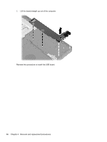
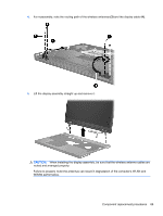
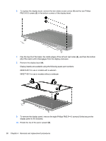
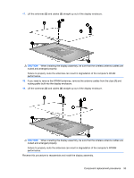
6. To replace the display bezel, remove the two rubber screw covers (1) and the two Phillips PM2.5×5.0 screws (2) in the bottom corners of the display bezel. 7. Flex the top (1) of the bezel, the inside edges of the left and right sides (2), and then the bottom (3) of the bezel until it disengages from the display enclosure. 8. Remove the display bezel (4). Display bezels are available using the following spare part numbers: 660276-001 for use in models with a webcam 660277-001 for use in models without a webcam 9. To remove the display panel, remove the eight Phillips PM2.5×4.0 screws (1) that secure the display panel to the brackets. 10. Rotate the top of the panel upward (2). 90 Chapter 4 Removal and replacement procedures
-
 1
1 -
2
-
3
-
4
-
5
-
6
-
7
-
8
-
9
-
10
-
11
-
12
-
13
-
14
-
15
-
16
-
17
-
18
-
19
-
20
-
21
-
22
-
23
-
24
-
25
-
26
-
27
-
28
-
29
-
30
-
31
-
32
-
33
-
34
-
35
-
36
-
37
-
38
-
39
-
40
-
41
-
42
-
43
-
44
-
45
-
46
-
47
-
48
-
49
-
50
-
51
-
52
-
53
-
54
-
55
-
56
-
57
-
58
-
59
-
60
-
61
-
62
-
63
-
64
-
65
-
66
-
67
-
68
-
69
-
70
-
71
-
72
-
73
-
74
-
75
-
76
-
77
-
78
-
79
-
80
-
81
-
82
-
83
-
84
-
85
-
86
-
87
-
88
-
89
-
90
-
91
-
92
-
 93
93 -
 94
94 -
 95
95 -
 96
96 -
 97
97 -
 98
98 -
 99
99 -
 100
100 -
 101
101 -
 102
102 -
 103
103 -
104
-
105
-
106
-
107
-
108
-
109
-
110
-
111
-
112
-
113
-
114
-
115
-
116
-
117
-
118
-
119
-
120
-
121
-
122
-
123
-
124
-
125
-
126
-
127
-
128
-
129
-
130
-
131
-
132
-
133
-
134
-
135
-
136
 |
 |
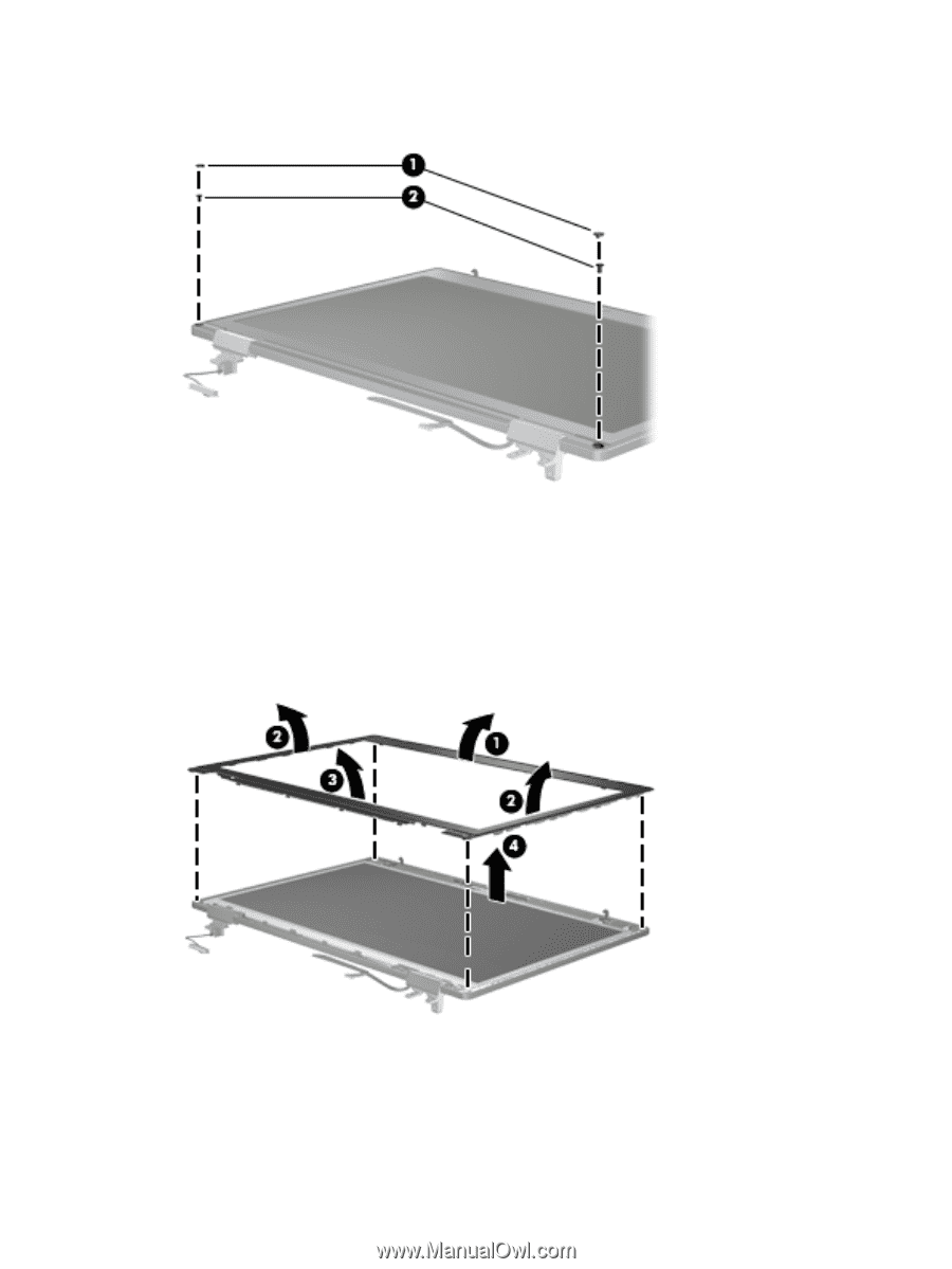
6.
To replace the display bezel, remove the two rubber screw covers
(1)
and the two Phillips
PM2.5×5.0 screws
(2)
in the bottom corners of the display bezel.
7.
Flex the top
(1)
of the bezel, the inside edges of the left and right sides
(2)
, and then the bottom
(3)
of the bezel until it disengages from the display enclosure.
8.
Remove the display bezel
(4)
.
Display bezels are available using the following spare part numbers:
660276-001 for use in models with a webcam
660277-001 for use in models without a webcam
9.
To remove the display panel, remove the eight Phillips PM2.5×4.0 screws
(1)
that secure the
display panel to the brackets.
10.
Rotate the top of the panel upward
(2)
.
90
Chapter 4
Removal and replacement procedures