HP ProLiant 1500 PCI Bus Numbering in a Microsoft Windows NT Environment - Page 47
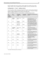
Table 15 illustrates the relationship between slot numbers, controller, installation
 |
View all HP ProLiant 1500 manuals
Add to My Manuals
Save this manual to your list of manuals |
Page 47 highlights
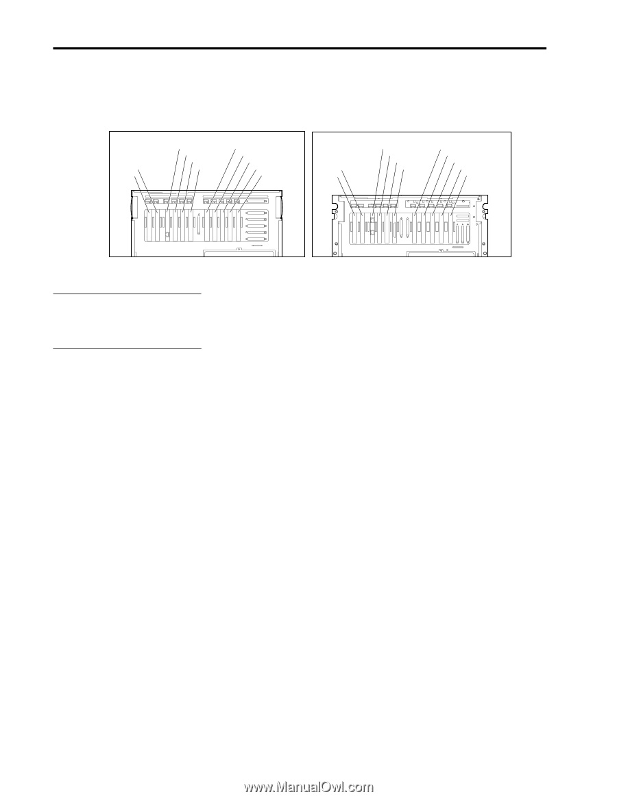
PCI Bus Numbering in a Microsoft Windows NT Environment 47 The diagrams in Figure 16 illustrate the location of the expansion slots in the rear of the ProLiant 6000 and 7000 servers. Both servers share the same bus design and slot layout; however, the ProLiant 7000 server contains hot pluggable slots on the Secondary Bus as shown in Figure 16. pat-10.eps EISA Slot 2 Slot 1 Primary PCI Bus Slot 3 Slot 4 Slot 5 Slot 6 Secondary PCI Bus Slot 7 Slot 8 Slot 9 Slot 10 Slot 11 EISA Slot 2 Slot 1 Standard PCI Slot 3 Slot 4 Slot 5 Slot 6 PCI Hot Plug Slot 7 Slot 8 Slot 9 Slot 10 Slot 11 Figure 16. Location of expansion slots in rear of the ProLiant 6000 and 7000 servers Bus number assignments for controllers with bridged devices are assigned to the device on the controller. Table 15 illustrates the relationship between slot numbers, controller installation, and PCI BIOS bus assignments in Configuration B-Test 1. This test includes several bridged controllers to demonstrate bus renumbering in a more complex configuration. 13UK-1200A-WWEN
-
 1
1 -
2
-
3
-
4
-
5
-
6
-
7
-
8
-
9
-
10
-
11
-
12
-
13
-
14
-
15
-
16
-
17
-
18
-
19
-
20
-
21
-
22
-
23
-
24
-
25
-
26
-
27
-
28
-
29
-
30
-
31
-
32
-
33
-
34
-
35
-
36
-
37
-
38
-
39
-
40
-
41
-
 42
42 -
 43
43 -
 44
44 -
 45
45 -
 46
46 -
 47
47 -
 48
48 -
 49
49 -
 50
50 -
 51
51 -
 52
52
 |
 |