HP ProLiant 1500 PCI Bus Numbering in a Microsoft Windows NT Environment - Page 50
Reviewing the Test 2 Configuration – Addition of Two Controllers
 |
View all HP ProLiant 1500 manuals
Add to My Manuals
Save this manual to your list of manuals |
Page 50 highlights
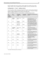
PCI Bus Numbering in a Microsoft Windows NT Environment 50 Reviewing the Test 2 Configuration - Addition of Two Controllers Configuration B−Test 2, illustrated in Table 15, provides an example of how the PCI BIOS discovers new controller devices that were not present in the original Test 1 configuration and how it assigns bus numbers during the discovery process. As in Test 1, the PCI BIOS moves through the bus detection order looking for controller devices (not the slot numbers). In this example, the PCI BIOS begins at the Host Bus and assigns bus 0 to the Primary Bus. Controllers that do not contain a bridge receive the bus number assignment of the bus on which it resides. In this scenario, the Netelligent 10/100 TX Controller in slot 3 does not have a bridge so it receives a bus assignment of bus 0. The PCI BIOS continues to search for the next device downstream on the Primary Bus. Two bridged controllers were added to the configuration. The PCI BIOS upon discovery of each controller assigns a bus number to the PCI bus on the bridged controller. Slot 4 now contains a SMART-2/P Drive Array Controller on bus 1 and slot 5 now contains a Dual 10/100TX PCI UTP Controller on bus 2. With the addition of these two new controllers in the system, all other controllers that are discovered by the PCI BIOS after slot 5 in the discovery process are now assigned a new bus number. The SMART-2/SL Drive Array Controller in slot 6, a bridged device, is discovered next. The PCI BIOS assigns bus 3 to the PCI bus on the controller, which changes the original bus number assignment. This is also the last PCI controller discovered on the Primary Bus. At this point, all bus number assignments on the Secondary Bus change when the PCI BIOS discovery process continues. The Secondary Bus is assigned bus 4. The controllers downstream on the Secondary Bus in slots 8 and 10 both contain bridges. Bus number assignments are made to the PCI buses on these bridged controllers. The SMART-2/SL Drive Array controller in slot 8 is assigned bus 5 and the Netelligent Dual 10/100 TX controller in slot 10 is assigned bus 4. Empty slots are ignored, because they do not contain PCI devices. Comparison of Test 1 to Test 2 - Configuration B When you reboot the server and run the System Configuration utility to view the hardware configuration changes, it displays slot and bus number assignments. Test 2 data was recorded and compared to Test 1. A side-by-side comparison of the slot configurations and bus numbers of each device in Test 1 to the slot configurations and bus numbers of each device in Test 2, illustrates what bus numbers were changed after modifications took place. Slot Controller Test 1 Test 2 Bus Assignment Slot 3 Netelligent 10/100 TX (non-bridged) $ $ Bus 0 - No Change Slot 4 SMART-2/P Drive Array (bridged) $ Bus 1 - New Slot 5 Netelligent Dual 10/100 TX (bridged) $ Bus 2 - New Slot 6 SMART-2/SL Drive Array (bridged) $ $ Bus 1 to Bus 3 - Changed Slot 7 Empty Slot 8 SMART-2/SL Drive Array (bridged) N/A $ $ Bus 3 to Bus 5 - Changed Slot 9 Empty Slot 10 Netelligent Dual 10/100 TX (bridged) N/A $ $ Bus 4 to Bus 6 - Changed Slot 11 Empty N/A 13UK-1200A-WWEN
-
 1
1 -
2
-
3
-
4
-
5
-
6
-
7
-
8
-
9
-
10
-
11
-
12
-
13
-
14
-
15
-
16
-
17
-
18
-
19
-
20
-
21
-
22
-
23
-
24
-
25
-
26
-
27
-
28
-
29
-
30
-
31
-
32
-
33
-
34
-
35
-
36
-
37
-
38
-
39
-
40
-
41
-
42
-
43
-
44
-
 45
45 -
 46
46 -
 47
47 -
 48
48 -
 49
49 -
 50
50 -
 51
51 -
 52
52
 |
 |